
User`s manual
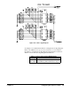
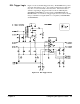

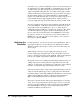

ECL Trigger Logic Figure 2-27 shows the ECL Trigger Circuitry. The ECLTRG lines provide
an intermodule timing resource. Any module, including the Slot 0 module,
may drive or receive information from these lines. The asserted state is
defined as logical high. Trigger information from the VXI backplane
(ECLTRG0 and ECLTRG1) pass through U1 to ECLTRGOUT0* and
ECLTRGOUT1* for custom use. Trigger inputs from user custom circuitry
must provide ECL level signals (TTL is not compatible) to ECLTRGIN0
and ECLTRGIN1.
Figure 2-27. ECL Trigger Circuit
Chapter 2 Configuring the Agilent E1490C 45