
User`s manual
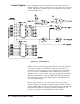
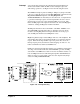


If its own level is not being acknowledged, or if the module is not asserting
IRQ, the state machine passes the daisy-chained IACKIN* signal through
IACKOUT on U9. The IACKOUT signal is gated with an inverted AS* to
meet release time requirements for IACKOUT* as outlined in the VMEbus
Specification. If the acknowledge level matches the request level, the IRQ
state machine sets PIACK* true, releases IRQX (and IRQ1*) and starts the
DTACK state machine for a read cycle. PIACK* going true also clears the
IRQ latch, U15. The interrupt handler initiates the read cycle to get the
logical device address from the interrupter when it sees IRQ1* go false.
PIACK* true enables U10 to place the module’s logical address (from SP1)
onto the lower eight bits of the internal data bus (DB0 - DB7). The logical
address is then transferred to backplane lines D0 - D7 during the read data
transfer cycle. In this way, the interrupt handler knows which device is
asserting IRQ if more than one device has the same interrupt priority
assigned to it.
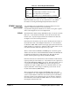
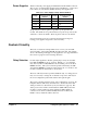
Control Table 2-9 shows the control signals which are implemented (see Appendix B):
Table 2-9. Control Signals
Signal Definition
AS* Address Strobe, used in the IRQ data transfer cycles.
DS0*, DS1* Data Strobes, used in the data transfer cycles.
SYSCLK Provides 16 MHz clock signals to the PAL (U1) for clocking the state
machines.
SYSFAIL* The module can assert this line to the backplane by setting bit SR2 low in
the Status Register. If the SYSFAIL INHBT line output of the Control
Register (bit 1) is also low (not inhibited), then SYSFAIL* is asserted.
SYSRESET* System reset signal used to initialize the backplane interface circuitry
(and your own custom circuits) to a known state. Provides a hardware
reset capability. As implemented (HRESET*), it clears the Status
Register and the Control Register. It also asserts the software reset line
(access point CRESET* on the module). CRESET* can also be asserted
via software by writing a high signal to the Control Register (bit 0),
providing an input to U2C.
44 Configuring the Agilent E1490C Chapter 2