
User`s manual
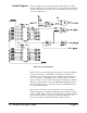
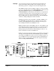


Interrupt A priority interrupt scheme has been implemented using the PAL (U9).
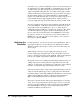
Another state machine within the PAL controls interrupt request and
acknowledge operations. See Figure 2-26 for the following discussion.
The VMEbus interrupt request levels IRQ1* - IRQ7* are jumper-selectable
(only one at a time allowed) for both the IRQ REQUEST output line and the
IRQ ACKNOWLEDGE input line. The IRQ REQUEST and
ACKNOWLEDGE levels must always be the same level. As implemented,
to generate an interrupt request to the interrupt handler, the user’s custom
circuits must provide a low-going signal at the IRQ* access point. This
latches the IRQ signal. The output of the Latch, U15, drives the IRQ input
on PAL U9, starting the IRQ state machine in the PAL.
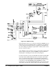
The IRQ state machine monitors the IACK*, valid DS0*, IACKIN*, AS*,
and ACKADDR* interrupt-related lines to determine its actions. If the
module is asserting IRQ and the interrupt-related lines are in the proper
state, the IRQ state machine asserts IRQX true on U9.
IRQX true pulls the jumper-selected IRQ1* line true on the backplane. The
state machine then waits for the interrupt handler to recognize the interrupt
request. When the interrupt handler responds, it places the code for the
interrupt request priority level that it is acknowledging onto lines A1 - A3.
It then sets IACK* true which sets IACKIN* true.
IACK* true starts the interrupt acknowledge cycle, disabling normal address
decoding on the breadboard module. When IACKIN* goes true, the IRQ
state machine sets DBEN true to latch A1-A3 into U6. Then it checks to see
if its own IRQ level has been acknowledged (input line ACKADDR at U9
will be set low by a correct match of U6’s decoded output and the jumper
selection for IRQ ACKNOWLEDGE).
Figure 2-26. Interrupt Circuitry
Chapter 2 Configuring the Agilent E1490C 43