
User`s manual
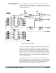
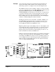


If the data transfer cycle is a write operation (as indicated by WRITE* true), an
additional state sets the U9 LATCH output low (enabling the Control Register
to receive data from the data bus drivers, for example) before DTACK* is set
true. The resulting Control Register outputs (CTL2 - CTL15) can then control
the user’s circuits, as desired.
Again, DTACK* going true tells the system controller that the data transfer
cycle is complete. In a write operation, WRITE* going true disables the
Status Register, the ID Register, and the Device Type Register.
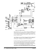
For both read and write operations, the DTACK state machine holds DTACK*
true and the address latched until the data strobes are invalid. After the data
strobes go invalid, the data bus drivers are disabled and the address latch is
released. In the next state, DTACK* is released and the state machine returns
to the idle state. If the DTACK INHibit signal (DTKINH) is set high
(hard-wired low on the Agilent E1490C implementation), the user can hold the
state machine in the first state of latched address and enabled data bus drivers.
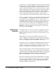
Figure 2-25. DTACK Circuitry
42 Configuring the Agilent E1490C Chapter 2