
User`s manual
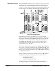
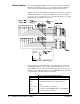
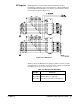

Status Register The 16-bit Status Register (Figure 2-21) provides specific status information
defined by the VXIbus System Specification, and has other bits available for
custom (device dependent) status information implemented by the user.
Table 2-3 shows the Status Register bit definitions. See pages 51 and 52 for
additional information on using the Status Register. Refer to the VXIbus
System Specification, Section C.2.1.1.2, for detailed information concerning
Status Register implementation restrictions.
The Status Register is enabled during a "read status register" operation by
the STATUS* enable line set low (decoded from address lines A1 - A3),
and by READ* set low. The status information presented to the data bus
line drivers (U24 and U25) must be static. The MODID line (P2, pin A30)
controls bit D14 of the Status Register at all times.
Table 2-3. Status Register Bit Definitions
Data Bit(s) Definitions
SR0 - SR1 Device Dependent (user assignable)
SR2 (0 = failed/executing Self-test; 1 = passed Self-test)
SR3 Ready
SR4 - SR13 Device Dependent (user assignable)
SR14 (0 = module selected by MODID high, 1 = not by MODID)
SR15 Device Dependent for A16 device
Figure 2-21. Status Register
36 Configuring the Agilent E1490C Chapter 2