
User`s manual


Metal Standoffs Metal standoffs (not provided with the module) can be installed to increase
the maximum component height above the printed circuit board or lead
length allowed below the printed circuit board. For example, if you are
wire-wrapping components to the PC board, you can install additional
standoffs to compensate for the long lead length of the wire-wrap sockets.
If you are using tall components, you can install additional standoffs to
compensate for the extra height requirement. With the standoffs installed,
the module will require an additional one or two mainframe slots, depending
on the length of the standoffs and whether you use standoffs on both sides
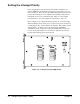
of the breadboard, or just on one side. Figure 2-6 shows the normal module
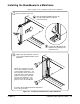
configuration and the module with standoffs installed (Figures 2-7 and 2-9).
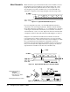
In Figure 2-7 the standoffs are installed between the PC board and the
bottom shield. The 19 mm hex standoff shown does not carry an Agilent
part number but can be ordered from the address shown in Figure 2-8. With
the recommended standoffs installed, this configuration extends the
maximum component lead length below the PC board from 3.2 mm (0.125
inch) to 22.2 mm (0.9 inch). Eight standoffs are required per module (all
eight standoffs are installed on the same side of the PC board).
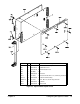
Figure 2-6. Agilent E1490C Without Spacers
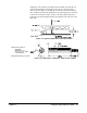
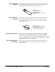
Manufacturer’s Address:
AMATOM
446 Blake Street
New Haven, CT 06515
1-800-243-6032
Quantity Required: 8 per module
Figure 2-7. Agilent E1490C With Short Standoffs Added
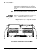
Figure 2-8. Dimensions of Amatom’s 19968-SS-350 Standoff
20 Configuring the Agilent E1490C Chapter 2