
User`s manual


Terminal Module
Connections
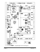
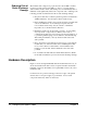
Figure 2-1 also shows the user connections and the terminal module. Refer
to pages 29 and 30 before attempting to wire the terminal module.
Ignore the pin numbers molded on the terminal module connectors; trace
your connection through the terminal module connector to ensure proper
wiring. The silkscreened pin numbers on the terminal module correspond to
the silk screened pin numbers on the breadboard module.
Connector J2 connects the breadboard module to the terminal module.
The silk screened numbers on the component side of the breadboard
(columns A, B, and C; row numbers 1 through 32) correspond to the pin
numbers on the J2 connector and the silkscreened numbers on the terminal
module (A20, B25, etc.). For example, A20 on the terminal module
matches to column A, row 20 on the breadboard module. Refer to the
breadboard schematics in Appendix B for additional pin wiring information.
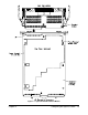
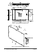
Module Dimensions
Figure 2-2 shows the dimensions of the module and the component height
and lead length restrictions. As shown, the maximum component height
allowed above the circuit board is 18.0 mm (0.71 inch). The maximum
component lead length allowed below the circuit board is 3.2 mm
(0.125 inch). If you need more lead length, provide insulation or add
standoffs as described on page 20. Do not mount components closer than 4
mm (0.16 inch) to the extreme upper or lower edges of the printed circuit
board. This space is used for shields and to guide the module into the
mainframe module slot. An area of 460 cm
2
(72 inch
2
) is available on the
module to install your own circuitry. This area does not include the portion of
the printed circuit board required to install the backplane interface components.
Figure 2-2. Agilent E1490C Dimensions
Chapter 2 Configuring the Agilent E1490C 17