
User`s manual


Backplane
Connections
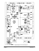
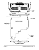
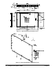
The breadboard module allows you to interface your custom circuits to any
standard C-size VXIbus backplane (connectors P1 and P2). This enables you
to access the backplane control signals, data lines, address lines, trigger buses,
and power supplies.
Backplane Connector
Pins
Table 2-1 lists backplane connectors P1 and P2 pins which connect to the VXIbus
backplane. Address memory or anything requiring A24 - A31 cannot be accessed
because there are no pins for the center row on the P2 connector. Data wider than
16-bits cannot be sent because the D16 - D31 lines are also on the center row.
Table 2-1. Backplane Connector Pins
Backplane Connector P1
Backplane Connector P2
P1 Pin
Row A
Mnemonic
Row B
Mnemonic
Row C
Mnemonic P2 Pin
Row A
Mnemonic
Row C
Mnemonic
1 D0 D08 1 ECLTRG0 CLK10+
2 D1 D09 2 –2V CLK10–
3 D2 ACFAIL* D10 3 ECLTRG1 GROUND
4 D3 BG0IN* D11 4 GROUND –5.2V
5 D4 BG0OUT* D12 5 LBUSA0 LBUSC0
6 D5 BG1IN* D13 6 LBUSA1 LBUSC1
7 D6 BG1OUT* D14 7 –5.2V GROUND
8 D7 BG2IN* D15 8 LBUSA2 LBUSC2
9 GROUND BG2OUT* GROUND 9 LBUSA3 LBUSC3
10 SYSCLK BG3IN* SYSFAIL* 10 GROUND GROUND
11 GROUND BG3OUT* 11 LBUSA4 LBUSC4
12 DS1* SYSRESET* 12 LBUSA5 LBUSC5
13 DS0* LWORD* 13 –5.2V –2V
14 WRITE* AM5 14 LBUSA6 LBUSC6
15 GROUND 15 LBUSA7 LBUSC7
16 DTACK* AM0 16 GROUND GROUND
17 GROUND AM1 17 LBUSA8 LBUSC8
18 AS* AM2 18 LBUSA9 LBUSC9
19 GROUND AM3 19 –5.2V –5.2V
20 IACK* GROUND 20 LBUSA10 LBUSC10
21 IACKIN* SERCLK 21 LBUSA11 LBUSC11
22 IACKOUT* SERDAT* 22 GROUND GROUND
23 AM4 GROUND A15 23 TTLTRG0* TTLTRG1*
24 A07 IRQ7* A14 24 TTLTRG2* TTLTRG3*
25 A06 IRQ6* A13 25 GROUND
26 A05 IRQ5* A12 26 TTLTRG4* TTLTRG5*
27 A04 IRQ4* A11 27 TTLTRG6* TTLTRG7*
28 A03 IRQ3* A10 28 GROUND GROUND
29 A02 IRQ2* A09 29
30 A01 IRQ1* A08 30 MODID GROUND
31 –12v +5STDBY +12v 31 GROUND +24V
32 +5v +5v +5v 32 SUMBUS –24V
16 Configuring the Agilent E1490C Chapter 2