
User`s manual


Chapter 2
Configuring the Agilent E1490C
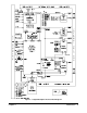
This chapter contains a detailed hardware description of the breadboard module
and discusses the backplane interface circuitry. It also shows a sample
application to control sixteen relays on the module. Chapter contents are:
• Handling Precautions . . . . . . . . . . . . . . . . . . . . . . . . . . . . . . . Page 13
• Hardware Description . . . . . . . . . . . . . . . . . . . . . . . . . . . . . . Page 14
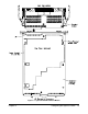
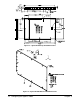
• Module Dimensions . . . . . . . . . . . . . . . . . . . . . . . . . . . . . . . . Page 17
• Cooling Requirements . . . . . . . . . . . . . . . . . . . . . . . . . . . . . . Page 22
• Setting the Logical Address Switch. . . . . . . . . . . . . . . . . . . . Page 23
• Setting the Interrupt Priority . . . . . . . . . . . . . . . . . . . . . . . . . Page 24
• Installing the Breadboard in a Mainframe . . . . . . . . . . . . . . . Page 25
• Terminal Modules . . . . . . . . . . . . . . . . . . . . . . . . . . . . . . . . . Page 26
• Wiring a Terminal Module . . . . . . . . . . . . . . . . . . . . . . . . . . Page 29
• Attaching a Terminal Module to the Breadboard . . . . . . . . . Page 31
• Backplane Interface Circuitry . . . . . . . . . . . . . . . . . . . . . . . . Page 32
• Custom Circuitry . . . . . . . . . . . . . . . . . . . . . . . . . . . . . . . . . . Page 47
Handling Precautions
WARNINGS, CAUTIONS, and guidelines to reduce the risk of static
discharge damage to the Agilent E1490C follow.
WARNING SHOCK HAZARD. Only qualified, service-trained personnel who
are aware of the hazards involved should install, remove, or
configure any module. Before you touch any installed module,
turn off all power to the mainframe and to all external devices
connected to the mainframe or to any of the modules.
For electrical shock protection, ensure that the module
faceplate is securely tightened against the mainframe.
WARNING Since inputs to the Agilent E1490C Breadboard Module are
through a 96-pin DIN connector and a terminal module
assembly, limit voltage to 250 Vdc/250 Vrms.
CAUTION STATIC SENSITIVITY. The backplane interface circuitry
described in this chapter uses static-sensitive CMOS integrated
circuit devices. If you implement the circuitry described herein,
you must use clean-handling and anti-static techniques when
handling the module to protect the sensitive components from
damage due to electrostatic discharge (ESD).
Chapter 2 Configuring the Agilent E1490C 13