Agilent 75000 SERIES C Agilent E1490C C-Size VXIbus Register-Based Breadboard Module User’s Manual *E1490-90004* Manual Part Number E1490-90004 Printed in Malaysia E0806
Contents Agilent E1490C User’s Manual Warranty . . . . WARNINGS . . Safety Symbols User Notes . . . . . . . . . . . . . . . . . . . . . . . . . . . . . . . . . . . . . . . . . . . . . . . . . . . . . . . . . . . . . . . . . . . . . . . . . . . . . . . . . . . . . . . . . . . . . . . . . . . . . . . . . . . . . . . . . . . . . . . . . . . . . . . . . . . . . . . . . . . . . . . . . . . . . . . . . . . 3 4 4 5 Chapter 1. Introduction . . . . . . . . . . . . . . . . . .
Chapter 2. Configuring the Agilent E1490C (continued) Device Type Register . . . . . Control Register . . . . . . . . DTACK, Interrupt, and Control DTACK . . . . . . . . . . . . Interrupt . . . . . . . . . . . . Control . . . . . . . . . . . . ECL Trigger Logic . . . . . . . User Access Points . . . . . . . Power Supplies . . . . . . . . . Custom Circuitry . . . . . . . . . Relay Selection . . . . . . . . . Notifying the Controller . . . . . . . . . . . . . . . . . . . . . . . . . . . . . . . . . . . . .
Certification Agilent Technologies certifies that this product met its published specifications at the time of shipment from the factory. Agilent Technologies further certifies that its calibration measurements are traceable to the United States National Institute of Standards and Technology (formerly National Bureau of Standards), to the extent allowed by that organization’s calibration facility, and to the calibration facilities of other International Standards Organization members.
Printing History The Printing History shown below lists all Editions and Updates of this manual and the printing date(s). The first printing of the manual is Edition 1. The Edition number increments by 1 whenever the manual is revised. Updates, which are issued between Editions, contain replacement pages to correct the current Edition of the manual. Updates are numbered sequentially starting with Update 1. When a new Edition is created, it contains all the Update information for the previous Edition.
Notes Agilent E1490C C-Sized VXIbus Register-Based Breadboard Module User’s Manual 5
Notes 6 Agilent E1490C C-Sized VXIbus Register-Based Breadboard Module User’s Manual
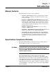
Chapter 1 Introduction Manual Contents This manual has three chapters and two appendixes: • Chapter 1 - Introduction summarizes manual contents, warranty status, specification compliance, and includes a description of the breadboard module. • Chapter 2 - Configuring the Agilent E1490C describes module hardware and dimensions, explains how to install the breadboard and terminal module, terminal module options, and discusses operation of the backplane interface circuits on the module.
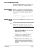
Agilent E1490C Description The Agilent E1490C Breadboard Module is a C-size register-based device that provides a convenient interface to a VXI mainframe backplane. It allows you to construct your own custom hardware for use with the mainframe. Breadboard Module Features The module provides VXI A16/D16 register-based backplane interface circuitry and metal shields to enclose the printed circuit board. Your VXI mainframe can communicate with this module configured as an A16/D16 device.
Figure 1-1.
• Status Register. Reading this 16-bit register provides information about the status of the breadboard module. Implemented signals are "A24/A32 Active", "MODID*", "Extended*" and "Passed". There are also provisions for implementing device-dependent status bits. See page 36 for information about the Status Register. • ID Register. Reading this 16-bit register identifies the manufacturer identification number, the device class, and the addressing mode of the breadboard.
Agilent E1490C Hardware Features An overview of the Agilent E1490C hardware features follows. • Connectors. A 96-pin DIN connector connects to the terminal module. Crimp-and-Insert terminal module connectors are available with Option A3E. • Component Area. An area of approximately 460 cm2 (72 inches2) is available on the module to install your own custom circuitry. This area does not include the portion of the circuit board required by the backplane interface components. • Component Height/Lead Length.
Notes 12 Introduction Chapter 1
Chapter 2 Configuring the Agilent E1490C This chapter contains a detailed hardware description of the breadboard module and discusses the backplane interface circuitry. It also shows a sample application to control sixteen relays on the module. Chapter contents are: • • • • • • • • • • • • Handling Precautions . . . . . . . . . . . . . . . . . . . . . . . . . . . . . . . Hardware Description . . . . . . . . . . . . . . . . . . . . . . . . . . . . . . Module Dimensions . . . . . . . . . . . . . . . . . .
Reducing Risk of Static Discharge Damage The smallest static voltage most people can feel is about 3500 V. It takes less than one-tenth of that (about 300 V) to destroy or severely damage static-sensitive circuits. Often, static damage does not immediately cause a malfunction, but significantly reduces the component’s life. Adhering to the following precautions will reduce the risk of static discharge damage. • Keep the module in its conductive plastic bag when not installed in a VXIbus mainframe.
Figure 2-1.
Backplane Connections The breadboard module allows you to interface your custom circuits to any standard C-size VXIbus backplane (connectors P1 and P2). This enables you to access the backplane control signals, data lines, address lines, trigger buses, and power supplies. Backplane Connector Pins Table 2-1 lists backplane connectors P1 and P2 pins which connect to the VXIbus backplane.
Terminal Module Connections Figure 2-1 also shows the user connections and the terminal module. Refer to pages 29 and 30 before attempting to wire the terminal module. Ignore the pin numbers molded on the terminal module connectors; trace your connection through the terminal module connector to ensure proper wiring. The silkscreened pin numbers on the terminal module correspond to the silk screened pin numbers on the breadboard module. Connector J2 connects the breadboard module to the terminal module.
Figure 2-3. Agilent E1490C Top Shield Dimensions Figure 2-4.
Location Qty. Part Number Description A1 1 E1490-66511 PC Breadboard Assembly MP1 1 E1400-45101 Top Extraction Lever MP2 1 E1400-45102 Bottom Extraction Lever MP3 1 8160-0686 Clip PNL1 1 E1490-00213 Front Panel SCR1 1 0515-1375 Front Panel Screw, M2.5 x 0.5, 6 mm long, flat head SCR2 - 3 2 E1400-00610 Shoulder Screw Assembly SCW8 - 15 8 0515-1135 Screw - M3 x 0.5, 25 mm long, flat head SHD1 1 E1490-00611 Top Shield SHD2 1 E1490-00612 Bottom Shield Figure 2-5.
Metal Standoffs Metal standoffs (not provided with the module) can be installed to increase the maximum component height above the printed circuit board or lead length allowed below the printed circuit board. For example, if you are wire-wrapping components to the PC board, you can install additional standoffs to compensate for the long lead length of the wire-wrap sockets. Figure 2-6.
In Figure 2-9 the standoffs are installed between the PC board and the top shield. The 30 mm hex standoff shown may also be ordered from the address shown in Figure 2-10. With the recommended standoffs installed, this configuration extends the maximum component height above the circuit board from 18 mm (0.71 inch) to 48 mm (1.89 inch). Eight standoffs are required per module (all eight standoffs are installed on the same side of the PC board). Figure 2-9.
Cooling Requirements The VXIbus System Specification requires module manufacturers to establish a cooling specification for each of their modules. The specification is to consist of: 1. the airflow required (in liters/second) for adequate cooling, and 2. the pressure drop that occurs across the module when the specified airflow is applied. Note Module cooling requirements are described in the VXIbus System Specification (Rev 1.4) in Section B.7.2.4.
Setting the Logical Address Switch The logical address switch (LADDR) factory setting is 232. Valid addresses are from 1 to 255. Refer to Figure 2-12 for switch position information. Figure 2-12.
Setting the Interrupt Priority For most applications where the breadboard module is installed in an Agilent 75000 Series C mainframe, the interrupt priority jumper does not have to be moved. This is because the VXIbus interrupt lines have the same priority, and interrupt priority is established by installing modules in slots numerically closest to the command module. Thus, slot 1 has a higher priority than slot 2, slot 2 has a higher priority than slot 3, and so on.
Installing the Breadboard in a Mainframe Refer to Figure 2-14 to install the breadboard in a mainframe. Set the extraction levers out. Slide the Agilent E1490C into any slot (except slot 0) until the backplane connectors touch. Seat the breadboard into the mainframe by pushing in the extraction levers. Tighten the top and bottom screws to secure the breadboard module to the mainframe. NOTE: The extraction levers will not seat the backplane connectors on older VXIbus mainframes.
Terminal Modules The Agilent E1490C Breadboard Module is comprised of a component PC board and a screw-type standard terminal module. If the screw-type terminal module is not desired, a crimp-and-insert terminal module (Option A3E) is available. See page 27 for information about the crimp-and-insert option and accessories. Note Screw-type Terminal Module Wiring Guidelines Refer to pages 29 and 30 before attempting to wire the terminal module.
Terminal Module Option A3E Crimp-and-Insert Terminal Module Accessories Option A3E can be ordered if a crimp-and-insert terminal module is desired. This allows you to crimp connectors onto wires which are then inserted directly into the breadboard’s mating connector. Refer to the schematics in Appendix B to make the connections. The following accessories are necessary for use with crimp-and-insert Option A3E: Figure 2-16.
Jumper Wire and Contacts A crimp-and-insert contact is crimped onto each end of a single conductor jumper wire. This jumper is typically used to tie two pins together in a single crimp-and-insert connector. Order Agilent 91512A. Length: 10 cm Wire Gauge: 24 AWG Quantity: 10 each Insulation Rating: 105°C maximum Voltage: 300 V Crimp-and-Insert Contacts These contacts may be crimped onto a conductor and then inserted into a crimp-and-insert connector.
Wiring a Terminal Module The following illustrations show how to connect field wiring to the terminal module. Remove Clear Cover Remove and Retain Wiring Exit Panel(s) Make Connections Install Connector (Crimp-and-Insert) Route Wiring Figure 2-17.
Replace Wiring Exit Panel(s) Replace Clear Cover Install the Terminal Module Push in the Extraction Levers to Lock the Terminal Module onto the Breadboard Figure 2-17.
Attaching a Terminal Module to the Breadboard Extend the extraction levers on the Align the terminal module connectors to the Agilent E1490C breadboard module. Apply gentle pressure to attach the terminal module to the breadboard module. Push in the extraction levers to lock the terminal module onto the breadboard module. To remove the terminal module from the Agilent E1490C breadboard, use a small screwdriver to release the two extraction levers.
Backplane Interface Circuitry The backplane interface circuitry allows you to access the backplane control signals, data lines, address lines, trigger buses, and power supplies.
Figure 2-19.
Either of the two address modifier hexadecimal codes indicated above will establish A16 addressing per the VXIbus System Specification (Section C.2.1.1.5). In the VXIbus addressing scheme for an A16 device, A14 and A15 are always set to 1 to select the upper 16K of the 64K A16 address space (per the VXIbus System Specification, Sections A.2.3.3 and C.2.1.1.1). LWORD* is false when decoding short word (16-bit) transfers. If a second match occurs at U17, its output goes low.
Data Bus Drivers The Agilent E1490C breadboard module is designed to be used as an A16 and a D16 device only. As such, only backplane address lines A1 - A15 and data lines D0 - D15 have been implemented on the module. VXIbus backplane connector J1 contains 16 bi-directional data lines labeled D0 through D15. The module connects to these data lines using the circuitry shown in Figure 2-20. Figure 2-20. Data Bus Drivers Data buffering is provided for the data lines by two tri-state octal bus transceivers.
Status Register The 16-bit Status Register (Figure 2-21) provides specific status information defined by the VXIbus System Specification, and has other bits available for custom (device dependent) status information implemented by the user. Table 2-3 shows the Status Register bit definitions. See pages 51 and 52 for additional information on using the Status Register. Refer to the VXIbus System Specification, Section C.2.1.1.
ID Register The ID Register is a 16-bit register which identifies the module’s manufacturer, addressing mode, and classification. These identification fields are DIP switch selectable on the inputs to the data bus line drivers U11 and U12 as shown in Figure 2-22. Figure 2-22. ID Register Table 2-4 shows the ID Register bit definitions, Table 2-5 shows possible Addressing Modes, and Table 2-6 shows the Device Classes as defined in the VXIbus System Specification (Section C.2.1.1.2). Table 2-4.
Each bit in the ID Register is normally pulled high (1) by RP5 and RP6. The bits can be reconfigured low by closing the appropriate switch (SP2 and SP3). If no switches are closed (that is, all bits are high or 1’s) from Tables 2-5 and 2-6, the module will be defined as a register-based and A16 device and will have a Manufacturer ID code of 4095 (Agilent Technologies). Table 2-5. Breadboard Addressing Mode Value Addressing Mode 00 A16/24 01 A16/32 10 RESERVED 11 A16 Only Table 2-6.
Figure 2-23. Device Type Register See Chapter 3 for additional information on using the Device Type Register. Refer to the VXIbus System Specification, Section C.2.1.1.2 for detailed information concerning Device Type Register implementation restrictions. Table 2-7 shows the Device Type Register bit definitions. Table 2-7.
Control Register The Control Register is a 16-bit register which, when written to from the backplane data bus, causes specific actions to be executed by the breadboard module. The primary components of the Control Register are U22 and U23 as shown in Figure 2-24. Figure 2-24. Control Register Table 2-8 shows the Control Register bit definitions. The Control Register is selected for writing to by the BASE + 4 enable line (see Table 2-2).
Table 2-8. Control Register Bit Definitions Data Bit(s) Definitions CR0 (1 = Reset the module, User defines reset actions) CR1 (1 = inhibit setting of SYSFAIL*; if Reset = 1, safe) CR2 - CR14 Device Dependent (User Assignable) CR15 (1 = Enable access to A24/A32 Registers; 0 = Disable) See pages 54 and 55 for additional information on using the Control Register. Refer to the VXIbus System Specification, Section C.2.1.1.
Figure 2-25. DTACK Circuitry If the data transfer cycle is a write operation (as indicated by WRITE* true), an additional state sets the U9 LATCH output low (enabling the Control Register to receive data from the data bus drivers, for example) before DTACK* is set true. The resulting Control Register outputs (CTL2 - CTL15) can then control the user’s circuits, as desired. Again, DTACK* going true tells the system controller that the data transfer cycle is complete.
Interrupt A priority interrupt scheme has been implemented using the PAL (U9). Another state machine within the PAL controls interrupt request and acknowledge operations. See Figure 2-26 for the following discussion. The VMEbus interrupt request levels IRQ1* - IRQ7* are jumper-selectable (only one at a time allowed) for both the IRQ REQUEST output line and the IRQ ACKNOWLEDGE input line. The IRQ REQUEST and ACKNOWLEDGE levels must always be the same level.
If its own level is not being acknowledged, or if the module is not asserting IRQ, the state machine passes the daisy-chained IACKIN* signal through IACKOUT on U9. The IACKOUT signal is gated with an inverted AS* to meet release time requirements for IACKOUT* as outlined in the VMEbus Specification. If the acknowledge level matches the request level, the IRQ state machine sets PIACK* true, releases IRQX (and IRQ1*) and starts the DTACK state machine for a read cycle.
ECL Trigger Logic Figure 2-27 shows the ECL Trigger Circuitry. The ECLTRG lines provide an intermodule timing resource. Any module, including the Slot 0 module, may drive or receive information from these lines. The asserted state is defined as logical high. Trigger information from the VXI backplane (ECLTRG0 and ECLTRG1) pass through U1 to ECLTRGOUT0* and ECLTRGOUT1* for custom use. Trigger inputs from user custom circuitry must provide ECL level signals (TTL is not compatible) to ECLTRGIN0 and ECLTRGIN1.
User Access Points The breadboard module contains traces (stubs) for accessing many of the signal lines on backplane connectors P1 and P2. Table 2-10 shows the signal lines that are brought onto the module but not implemented. They are available as signal access points for your custom circuits. Table 2-10.
Power Supplies Table 2-12 lists the power supply pins available from the P1 and P2 connectors. The + 5 and – 5.2 Vdc interface supplies are fused and filtered (– 2 Vdc is used but not fused). You should fuse and filter all other power supplies used. Table 2-12. Power Supply Voltage and Pin Numbers Voltage P1 Connector Pin Numbers Voltage P2 Connector Pin Numbers +5Vdc A32, B32, C32 –5.
Since this is a write operation, LATCH* goes true for one clock cycle as part of the data transfer cycle. With both BASE + 8 and LATCH* set low, the output of U101A briefly goes high, clocking the relay selection bit pattern onto the outputs of U105 and U106, which are not yet enabled. The outputs of U105 U108 are enabled by the following path. The output of U101A is also applied through U101B to U103A, a monostable multivibrator.
FROM AGILENT TECHNOLOGIES.
Chapter 3 Using the Agilent E1490C This chapter shows how to use the backplane interface circuitry on the Agilent E1490C Breadboard Module. This chapter includes: • • • • • • • Reading Data From Registers . . . . . . . . . . . . . . . . . . . . . . . . Writing Data to the Control Register . . . . . . . . . . . . . . . . . . . Using Interrupts . . . . . . . . . . . . . . . . . . . . . . . . . . . . . . . . . . . Resetting the Module . . . . . . . . . . . . . . . . . . . . . . . . . . . . . . .
Figure 3-1. Status Register Access Points Reading the Status Register For example, assume you need to use up to 16-bits of the Status Register, including latching the data in both halves of the register. To latch your status data and then read the 16-bit contents of the Status Register onto the backplane, you must implement the following signal and control lines: 1. Address the module correctly by placing the data shown in Table 3-2 on the backplane address lines: 2.
Figure 3-2. Timing for Reading the Status Register Reading ID and Device Type Registers The procedure to read the ID and Device Type Registers is the same as that for the Status Register with two exceptions: 1. the contents of these two registers are set by switches; and 2. the address enable line used is different (see Table 2-1 on page 16).
Writing Data to the Control Register The breadboard module contains circuitry for a Control Register. You can write to this register from the backplane over data lines D0 - D15. The data is passed to the internal data bus DB0 - DB15 and then clocked into the Control Register for use by the custom circuitry on the breadboard at access points CTL2 - CTL15. Do not tie anything here that cannot tolerate having a "1" written to it with software reset or do not use software reset. See page 59.
Writing to the Control Register To write to the Control Register from the backplane data lines, you must implement the following signal and control lines: 1. Address the module correctly by placing the data shown in Table 3-4 on the backplane address lines: Table 3-4. Backplane Address Lines (Control Register) Lines Data Required Lines A1-A3 Must be set low/high/low (010) to select the BASE+4 enable line.
Figure 3-4.
Using Interrupts The breadboard module can be configured to generate an interrupt to the interrupt handler when service is required. Configuring for Interrupts To configure the module to generate interrupts, you must first assign an interrupt priority level to the module. Levels 1-7 are available, with level 7 being the highest level.
Figure 3-5.
Resetting the Module A reset signal is provided to initialize the backplane interface circuit and your own custom-designed circuitry to a known state. Both hardware and software resets are implemented for your convenience. Hardware Reset The backplane SYSRESET* line drives both the hardware reset (HRESET*) and the software reset (CRESET*) user access points low (0) on the breadboard module.
Using Other Power Supplies You can use any of the other power supply voltages from a standard VXIbus backplane as described in the VXIbus Specification. All of the available voltages have been stubbed onto the breadboard module as user access points. Just remember that you must provide your own fusing and filtering on board the module for each power supply you access from the backplane.
Example Programs This section shows example programs to read the ID and Device Type Registers and write to the Control Register. Reading the Registers Register Definitions The examples in this section show how to use the VXI:READ? command to read the ID and Device Type Registers. Reading the Status Register is similar. ID Register: Reading the ID Register (register 00h) returns FFFFh which indicates the manufacturer is Agilent Technologies and the module is an A16 register-based device.
Reading/Writing to Custom Registers 62 As you add your own custom registers to the breadboard, use the REG0* through REG4* enable lines. These lines address registers 6, 8, A, C, E, respectively. You can read or write to your registers using the same procedures shown by substituting the correct register address.
Appendix A Agilent E1490C Breadboard Specifications Agilent E1490C Breadboard module specifications follow. Item Specification User Component Area 490 cm2 (76 inches2) Grid Hole Spacing 2.54 mm (0.1 inch) Grid Hole Inside Diameter 1.17 mm (0.046 inch) Maximum Component Height 18.0 mm (0.71 inch) above PC board Maximum Lead Length 3.2 mm (0.125 inch) below PC board Maximum Power Dissipation Determined by mainframe cooling.
Notes 64 Agilent E1490C Breadboard Specifications Appendix A
Appendix B Agilent E1490C Parts List, Component Locator, and Schematics Table B-1 lists the Agilent E1490C backplane interface circuitry components. See pages 68 through 71 for the schematics. To order a part, contact Agilent Technologies or the vendor listed in Table B-2 and quote the manufacturer’s part number, desired quantity, and the description. Table B-1. Agilent E1490C Breadboard Parts List Reference Designator Agilent Part Number Total Qty. C1 – C12 0160-4832 12 Capacitor .
Table B-1. Agilent E1490C Breadboard Parts List (continued from previous page) Reference Designator Agilent Part Number Total Qty. U15 – U16 1820-4242 2 IC-Schmitt-Trigger 34371 CD74HCT14E U17 – U18 1820-3631 2 IC-Comparator 27014 MM74HCT688N U19 – U20 1820-3714 2 IC-Transceiver 01295 SN74ALS245A-1N U21 1820-3081 1 IC-FF CMOS 01295 SN74HC74N U22 –U23 1820-3399 2 IC-FF CMOS 01295 SN74HC273N Description Mfr. Code Mfr. Part Number Table B-2.
E1490-66511 Component Locator (Rev.
Appendix B Agilent E1490C Schematics 68
Appendix B Agilent E1490C Schematics 69
Appendix B Agilent E1490C Schematics 70
Appendix B Agilent E1490C Schematics 71
Index Agilent E1490C User’s Manual A Access Points control register, 54 status register, 52 ACKADDR, 43 Address decode circuitry, 35 lines, 8, 32 lines, backplane, 52, 55 logical, 23, 32 modes, 38 modifier lines, 8 strobe, 44 Airflow Requirements, 22 AS*, 44 Asterisk, meaning of, 8, 32 Attaching breadboard to mainframe, 25 terminal module, 31 B Backplane buffering, 10 connections, 16 connector pins, 16 schematic, 69 control register address lines, 55 interface circuitry, 32 interface features, 8 status re
C (continued) Control Signals, 44 Cooling Requirements, 22 CRESET*, 44, 59 access point, 59 Crimp-and-Insert accessories, 27 connectors, 28 contacts, 27 - 28 option A3E, 11 tools, 28 Custom Circuitry, 47 - 49 controller notification, 48 relay selection, 47 D Data buffering, 35 bus drivers, 8, 35 enable (DBEN), 35, 41 lines, 8, 35 reading from registers, 51 strobe lines, 41, 44 transfer acknowledge circuitry, 41 signal, 10 writing to control register, 54 - 55 DBEN, 35, 41 Description, 8 Detecting Errors, 59
I (continued) Interrupt circuitry, 43 configuring for, 57 interface, 10 priority, 10, 24, 43, 57 request levels, 43, 57 requests, generating, 57 using, 57 Inverse Logic, 8 IRQ ACKNOWLEDGE input line, 43, 57 jumper, 24, 43, 57 REQUEST output line, 43, 57 J Jumpers, interrupt priority, 24, 43, 57 L LADDR, 23 LATCH, 55 output low, 42 LATCH*, 40 Lead Length, 11, 17 Logical Address, 23 LWORD*, 34 M Mainframe cooling requirements, 22 installing breadboard, 25 Maximum component height, 11, 63 component lead len
S (continued) Status Register (continued) reading, 10, 36, 52 timing for reading, 53 STATUS*, 36, 40 Stubs, 46 SYSCLK, 40 - 41, 44 SYSFAIL INHBT, 44 SYSFAIL*, 44 SYSRESET*, 44, 59 T Terminal Block See Terminal Module Terminal Module attaching to breadboard, 31 connections, 17, 26, 29 - 30 crimp-and-insert option, 11, 27 - 28 description, 26 maximum current, 63 options, 11, 27 - 28 screw-type, 26 wiring, 26, 29 - 30 guidelines, 26 Timing control register writing, 56 status register reading, 53 U User Acces