
Technical data

3- 4 Agilent B2900A Configuration and Connection Guide, Edition 1
Connection
Connection with Test Fixture
3.2 Connection with Test Fixture
This section describes how to connect with Test Fixture to the Agilent B2900A
source/measure terminals. For details of each fixture, refer to the user’s guide of each test
fixtures also.
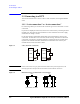
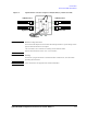
3.2.1 To use N1295A Test Fixture
The Agilent N1295A is a test fixture which has four triaxial connectors which supports
2-wire connections. To connect the N1295A to the B2900A source/measure terminals, the
Agilent N1294A-001 banana to triaxial adapter for the 2-wire connection is required.
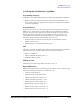
• Connection example for two terminals device
To connect to the N1295A test fixture for the device of two terminals, two 16494A
Triaxial cables are required.
Figure 3-5 Agilent N1295A connection example for the device with two terminals
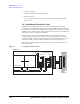
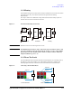
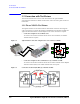
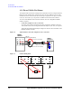
• Connection example for three terminals device by 2 channels of SMU
To connect to the N1295A test fixture for the device of three terminals such as Bipolar
Junction Transistor (BJT), four 16494A Triaxial cables are required.
Figure 3-6 Connection circuit for BJT (NPN) by 2 channels of SMU
1
1
2
3
4
3
2
4
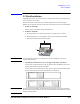
± 42V 1.05 A Max
Low Force
High Force
DUT