
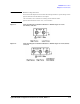
Technical data

Agilent B2900A Configuration and Connection Guide, Edition 1 2- 11
B2900A Accessories
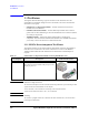
Other I/F and Interlock
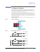
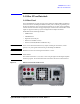
2.4 Other I/F and Interlock
2.4.1 Rear Panel
The Agilent B2900A rear panel provides various interfaces. GPIB, USB2.0 and Ethernet
(LAN) are used for controlling the B2900A remotely with or without programming. The
D-sub 25 pin digital I/O port is general purpose interface. It provides various capabilities
used for external control such as trigger input/output, interlock control and handler control
signals. It supports to build up a system configured from multiple instruments.
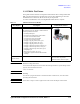
The B2900A has the following Interfaces.
• GPIB Interface
• USB-B Interface
• Digital I/O (D-sub 25 pin)
• Ethernet (10/100 Bast-T LAN)
• Channel 2 terminal (B2902A and B2912A only)
CAUTION Never connect the Guard terminal to any output, including circuit common, chassis
ground, or any other guard terminal. Doing so will damage the B2900A.
CAUTION Maximum current to the chassis ground terminal is 3 A DC.
NOTE Serial Number
You need the instrument’s serial number when using the Agilent Technologies telephone
assistance program. The serial number label is attached to the bottom of the instrument.
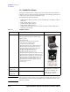
Figure 2-5 B2912A (2-channel model) Rear View