
Technical data

Agilent B2900A Configuration and Connection Guide, Edition 1 2- 9
B2900A Accessories
Test Fixture
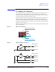
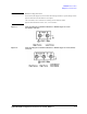
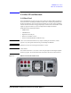
2.3.2 U2941A Test Fixture
The Agilent U2941A test fixture is designed for semiconductor device testing and has three
BNC type input channels and a common guard. You can select different types of socket
modules for devices-under-test (DUTs) of various pin conjunctions.
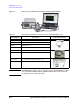
To connect to the B2900A, 1253-7217 Plug-Banana Double (black) is required.
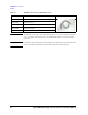
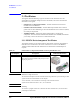
Table 2-6 U2941A Parametric Test Fixture
CAUTION Maximum voltage and current
The test fixture and adapters must be used under the following limitations to prevent damage to them.
Agilent U2941A Parametric test fixture:
±60 V, 1 A maximum
NOTE Shielding
The U2941A is quipped with the lid. To minimize the affect of ambient noise, close the lid when
performing the measurement.
NOTE Ensure that no voltage or current is applied to the U2941A when attaching the socket module.
Model/Option Description Additional Information
U2941A Parametric Test Fixture
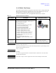
The following items are shipped as standard with the
U2941A parametric test fixture.
• Assembly PTFE plate
• 28-pin dual-in-package (DIP) socket module
• 0.1-inch universal socket module
• 0.075-inch universal socket module
• 0.5-inch universal socket module
• Pin plug-to-pin plug cables, black (4 pcs)
• Pin plug-to-pin plug cables, red (4 pcs)
• Pin plug-to-pin plug cables, blue (4 pcs)
• Pin plug-to-miniature clip cables, black (4 pcs)
• Pin plug-to-miniature clip cables, red (4 pcs)
• Pin plug-to-miniature clip cables, blue (4 pcs)
• PCB jumper pin
• BNC to two-wire cable, 1m (3 pcs)
• CD-ROM for Agilent Parametric Measurement
Manager
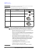
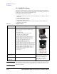
U2941A-107
(U2941-61601)
BNC to two-wire cable (1 m) The U2941A includes three BNC to
two-wire cables. If you need
additional cables, select this option.