
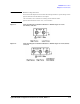
Technical data

2-8 Agilent B2900A Configuration and Connection Guide, Edition 1
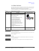
B2900A Accessories
Test Fixture
2.3 Test Fixture
The Agilent offers the following 3 types of test fixture. Each Test fixture have the
specification for maximum voltage and current. For details, refer to the each technical
document or user’s guide.
• N1295A Device/component Test Fixture - has four triaxial connectors for four
terminal devices as maximum.
• U2941A Parametric Test Fixture - has three BNC input channels and a common
ground. You can select different types of socket modules for device-under-test (DUTs)
of various pin conjunctions.
• 16442B Test Fixture - designed for testing packaged device and electronic
components. You can mount the suitable socket module on the 16442B, which allows
you to easily connect various devices to measurement units.
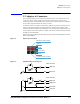
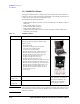
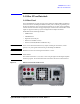
2.3.1 N1295A Device/component Test Fixture
The Agilent N1295A is a test fixture which has four triaxial connectors which allows to
make two 2-wire connections or the 4-wire connections. To connect to the B2900A,
16494A Triaxial cables and either N1294A-001 or 002 banana to triaxial adapter are
required.
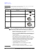
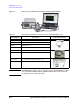
Table 2-5 N1295A Device/component Test Fixture for the Agilent B2900A series
CAUTION Maximum voltage and current
The test fixture and adapters must be used under the following limitations to prevent damage to them.
Agilent N1294A-001 and 002 Banana to Triax adapter:
±250 V maximum, ±42 V maximum for connecting N1295A Small test fixture.
Agilent N1295A Small Test Fixture: ±42 V, 1.05 A maximum
NOTE Shielding
The N1295A is quipped with the lid. To minimize the affect of ambient noise, close the lid when
performing the measurement.
Model/Option Description Additional Information
N1295A Device/component Test Fixture
The N1295A test fixture furnishes with pin clip wire 4 ea.
and pin plug wire 2 ea.