Agilent B2900A Series Precision Source/Measure Unit Configuration and Connection Guide Agilent Technologies
Notices © Agilent Technologies, Inc. 2011 Manual Part Number No part of this manual may be reproduced in any form or by any means (including electronic storage and retrieval or translation into a foreign language) without prior agreement and written consent from Agilent Technologies, Inc. as governed by United States and international copyright laws. B2900-90090 Edition Edition 1, May 2011 Agilent Technologies, Inc. 5301 Stevens Creek Blvd Santa Clara, CA 95051 USA defined in FAR 2.
Contents 1. B2900A Product Configuration Product Line up of the B2900A Series . . . . . . . . . . . . . . . . . . . . . . . . . . . . . . . . . 1-2 Options of B2900A Series . . . . . . . . . . . . . . . . . . . . . . . . . . . . . . . . . . . . . . . . . . . 1-3 Furnished Accessories . . . . . . . . . . . . . . . . . . . . . . . . . . . . . . . . . . . . . . . . . . . . . . 1-4 2. B2900A Accessories Cables. . . . . . . . . . . . . . . . . . . . . . . . . . . . . . . . . . . . . . . . . . . . . . . . . . . .
Contents To make connection to reduce leakage current . . . . . . . . . . . . . . . . . . . . . . . . Guarding . . . . . . . . . . . . . . . . . . . . . . . . . . . . . . . . . . . . . . . . . . . . . . . . . . . . To make connection to measure low resistance . . . . . . . . . . . . . . . . . . . . . . . . Kelvin Connection . . . . . . . . . . . . . . . . . . . . . . . . . . . . . . . . . . . . . . . . . . . . 3-15 3-15 3-16 3-16 4. Ordering Examples Agilent B2900A for Resistance measurement. . . . . . .
1 B2900A Product Configuration
B2900A Product Configuration Product Line up of the B2900A Series 1.1 Product Line up of the B2900A Series The Agilent B2900A Series of Precision Source/Measure Unit provides wider voltage and current coverage, higher resolution, and graphical user interface for more quicker test, debug and characterization on the bench top.
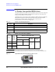
B2900A Product Configuration Options of B2900A Series 1.2 Options of B2900A Series This section describes Option items of the Agilent B2900A Series Precision Source/Measure Unit. Table 1-3 Option B2900A Options Description OP Instruction Specify the language of the paper manual if you need ABA Paper Manual (User’s Guide), English • Additional printed paper manual. (English) • The B2900A series product includes CD-ROM manuals.
B2900A Product Configuration Furnished Accessories 1.3 Furnished Accessories The B2900A is furnished with the accessories listed in the following table. Table 1-4 B2900A Options Description Qty.
2 B2900A Accessories
B2900A Accessories Cables 2.1 Cables The B2900A series has banana type output ports with Force, Sense and Guard potential. However, if you use conversion adapter, you can use BNC type cables or Triaxial cables so that each SMU channels can connect to dedicated test environment for DUT such as test fixture or wafer prober.
B2900A Accessories Cables Table 2-2 Model/Option BNC cables for the Agilent B2900A series Description 16493B-001 Coaxial Cable, BNC(m) to BNC(m), 1.5 m 16493B-002 Coaxial Cable, BNC(m) to BNC(m), 3.0 m Additional Information The maximum voltage is 40 V, and Maximum current is 200 mA. The Agilent 16493B Coaxial Cable is designed for use with VSU (Voltage Source Unit), VMU (Voltage Measurement Unit) or PGU (Pulse Generator Unit) on the Agilent 4155 series Semiconductor Parameter Analyzer.
B2900A Accessories Cables Table 2-3 Triaxial cables for the Agilent B2900A series Model/Option Description 16494A-001 Triaxial Cable, 1.5 m 16494A-002 Triaxial Cable, 3 m 16494A-003 Triaxial Cable, 80 cm 16494A-004 Triaxial Cable, 40 cm 16494A-005 Triaxial Cable, 4 m Additional Information CAUTION The maximum current rating of the 16494A Triaxial cable is 1A. Do not use the triaxial cable with over 1A.
B2900A Accessories Adapters & Connectors 2.2 Adapters & Connectors For connecting a DUT, you can choose the connection type 2-wire connection or 4-wire connections. If you want to simplify the connections, use the 2-wire connections by connecting the Force terminals only. Then open the Sense terminals. The Force terminals can be used to apply and measure dc voltage or current. To make the 4-wire connections, remote sensing, well known as Kelvin connections, uses both Force and Sense terminals.
B2900A Accessories Adapters & Connectors NOTE The following table shows the adapter information provided by Agilent. If you need and adapter which is not provided, contact a local parts vendor.
B2900A Accessories Adapters & Connectors CAUTION Maximum voltage and current The test fixture and adapters must be used under the following limitations to prevent damage to them. Agilent N1294A-001 and 002 Banana to Triax adapter: ±250 V maximum, ±42 V maximum for connecting N1295A Small test fixture. Agilent N1295A Small Test Fixture: ±42 V, 1.
B2900A Accessories Test Fixture 2.3 Test Fixture The Agilent offers the following 3 types of test fixture. Each Test fixture have the specification for maximum voltage and current. For details, refer to the each technical document or user’s guide. • N1295A Device/component Test Fixture - has four triaxial connectors for four terminal devices as maximum. • U2941A Parametric Test Fixture - has three BNC input channels and a common ground.
B2900A Accessories Test Fixture 2.3.2 U2941A Test Fixture The Agilent U2941A test fixture is designed for semiconductor device testing and has three BNC type input channels and a common guard. You can select different types of socket modules for devices-under-test (DUTs) of various pin conjunctions. To connect to the B2900A, 1253-7217 Plug-Banana Double (black) is required.
B2900A Accessories Test Fixture 2.3.3 16442B Test Fixture The Agilent 16442B test fixture is designed for testing packaged devices and electronic components. You can mount the suitable socket module on the 16442B, which allows you to easily connect various devices to measurement units. The 16442B has the following input ports. • 6 SMU channels (Triaxial connector. It can be used either for 6 non-Kelvin or 3 Kelvin connectors.
B2900A Accessories Other I/F and Interlock 2.4 Other I/F and Interlock 2.4.1 Rear Panel The Agilent B2900A rear panel provides various interfaces. GPIB, USB2.0 and Ethernet (LAN) are used for controlling the B2900A remotely with or without programming. The D-sub 25 pin digital I/O port is general purpose interface. It provides various capabilities used for external control such as trigger input/output, interlock control and handler control signals.
B2900A Accessories Other I/F and Interlock Figure 2-6 Remote control of B2912A by external PC (through USB/LAN/GPIB) Table 2-8 Item number information for related accessories used with B2900A series Model/Option Description 10833A GBIB cable, 1 m 10833B GBIB cable, 2 m 10833C GBIB cable, 4 m 10833D GBIB cable, 0.5 m 16493G-001 Digital I/O connection cable, 1.5 m 16493G-002 Digital I/O connection cable, 3.0 m N1294A-011 Interlock cable for 16442B Test Fixture, 1.
B2900A Accessories Other I/F and Interlock 2.4.2 Program and Interface Capabilities Programming Language The B2900A series supports SCPI (Standard Commands for Programmable Instruments). • Default command set: Supports all of the advanced features of the B2900A series • Conventional command set: Support industry standard conventional SCPI command set for basic compatibility.
B2900A Accessories Other I/F and Interlock • 5 V power supply pin: Limited to 600 mA, solid state fuse protected • Safety interlock pin: One active high pin and one active low pin. Activation of both pin enables output voltage > 42 V. 2.4.3 Installing the Interlock Circuit The B2900A cannot apply high voltage over ± 42 V when the Digital I/O interlock terminal is open.
B2900A Accessories Rack Installation 2.5 Rack Installation Agilent B2900A series can be mounted in a 19-inch EIA rack cabinet. It is designed to fit in two rack-units (2U) of space. Remove the handle and the front and rear rubber bumpers before rack mounting the B2900A. Do not block the air intake at the sides and the exhaust at the rear of the B2900A. 1. To Remove the Bumper Stretch a corner of the rubber bumper and slide it off. 2. To Remove the Handle a. Grasp the handle by the sides and pull outward.
B2900A Accessories Rack Installation 2-16 Agilent B2900A Configuration and Connection Guide, Edition 1
3 Connection
Connection Connecting to a DUT 3.1 Connecting to a DUT This section describes how to connect a device under test (DUT) to the Agilent B2900A series. 3.1.1 “2-wire connections” or “4-wire connections” For connecting a DUT, you can choose the connection type 2-wire connections or 4-wire connections. If you want to simplify the connection, use the 2-wire connections by connecting the Force terminals only. Then open the Sense terminals.
Connection Connecting to a DUT 3.1.2 Floating In the default setting, the Low Force and Low Sense terminals are connected to the chassis ground. However, they can be disconnected from the ground fro the floating measurements. This setup is effective for differential voltage measurements which usually require two channels as shown in the Grounded 2 connection.
Connection Connection with Test Fixture 3.2 Connection with Test Fixture This section describes how to connect with Test Fixture to the Agilent B2900A source/measure terminals. For details of each fixture, refer to the user’s guide of each test fixtures also. 3.2.1 To use N1295A Test Fixture The Agilent N1295A is a test fixture which has four triaxial connectors which supports 2-wire connections.
Connection Connection with Test Fixture Figure 3-7 Agilent N1295A connection example for the BJT (NPN) by 2 channels of SMU Low Force ch 1 Low Force ch 2 High Force ch 1 High Force ch 2 Emitter Collector CAUTION Base Maximum voltage and current The test fixture and adapters must be used under the following limitations to prevent damage to them. Agilent N1294A-001 Banana to Triax adapter: ±250 V maximum, ±42 V maximum for connecting N1295A Small test fixture.
Connection Connection with Test Fixture 3.2.2 To use U2941A Test Fixture The Agilent U2941A test fixture is designed for semiconductor device testing and has three BNC type input channels and a common guard. You can select different types of socket modules for devices-under-test (DUTs) of various pin conjunctions. See Agilent U2941A Parametric Test Fixture Operating Guide for details and accessories of the U2941A.
Connection Connection with Test Fixture • Connection example for 4-wire Connections To connect to the U2941A test fixture for 4-wire connections, two BNC to two-wire cable (U2941-61601) and two Plug-Banana Double adapter (1253-7217) are required. Attach the plug-banana double adapters to the B2900A source/measure terminals (High Force, Low Force, Low Force and Low Sense) as shown in the following figure.
Connection Connection with Test Fixture 3.2.3 To use 16442B Test Fixture The Agilent 16442B test fixture is designed for testing packaged devices and electronic components. The 16442B has six triaxial connectors for source/measure unit (SMU), the GNDU connector for the ground unit of a parameter/device analyzer, the Interlock connector for the interlock control, and six coaxial (BNC type) connectors for other instruments.
Connection Connection with Test Fixture • Connection example for 4-wire Connections To connect to the 16442B test fixture for 4-wire connections, N1294A-002 banana to triaxial adapter for 4 wire (kelvin) connection and three 16494A triaxial cables are required. Attach the banana to triaxial adapter to the B2900A source/measure terminals. Connect the triaxial cables between the adapter and the 16442B as shown in the following figure.
Connection Connection with Test Fixture • Connection example for three terminals device by 2 channels of SMU To connect to the 16442B test fixture for three terminals device by 2 channels of SMU, two sets of N1294A-001 banana to triaxial adapter for 2 wire (non-kelvin) connection and four 16494A triaxial cables are required. Attach the banana to triaxial adapter to the B2900A source/measure terminals. Connect the triaxial cables between the adapter and the 16442B as shown in the following figure.
Connection Connection with Test Fixture NOTE Shielding The 16442B is quipped with the lid. To minimize the affect of ambient noise, close the lid when performing the measurement. NOTE Performing high voltage measurement When the Digital I/O interlock terminal is open, the B2900A cannot apply high voltage over ±42 V. To perform the high voltage measurement, the B2900A must be connected to the interlock circuit installed in the 16442B. Prepare the N1294A-011 or 012 interlock cable.
Connection Connection with Prober 3.3 Connection with Prober This section describes information on how to connect a prober to the B2900A series Precision Source / Measure Unit. 3.3.1 Connecting to Manual Prober High Force and Low Force terminal on the N1294A-001 banana to triaxial adapter for 2-wire have FORCE (SENSE), GUARD, and COMMON output as shown Figure 3-18. High Force and High Sense on the he N1294A-002 banana to triaxial adapter for 4-wire also have same output terminals as shown Figure 3-18.
Connection Connection with Prober 4-wire (Kelvin) connection for High Force and High Sense These instructions apply when all connections are Kelvin. Two probes must contact the wafer in this connection. Connect two Agilent 16494A triaxial cables between the High Force and High Sense Terminals on the N1294A-002 banana to triaxial adapter for 4-wire and the connector plate. Connect the FORCE and SENSE lines to probes separately. Connect the triaxial connector on the probe cable as shown in Figure 3-21.
Connection Connection with Prober Item number information for 4-wire (Kelvin) connection for the Low terminal Table 3-1 Description Qty Product Number Part number Triaxial Cable (1.5 m) - Max 1.0 A 1 16494A-001 N/A Triaxial Cable (3.0 m) - Max 1.0 A 1 16494A-002 N/A Triax (m) to Triax (f) adapter 1 N1254A-107 1250-2654 Kelvin to non-Kelvin connection These instructions apply when the connections up to the Connector Plate are Kelvin, but the probe is a non-Kelvin connection.
Connection Connection with Prober 3.3.2 To make connection to reduce leakage current To reduce the leakage current caused by connection cables, the guard technique is effective. Connect the probing needles to the coaxial cables as shown below: Guarding reduces the leakage current between the instrument and a DUT. This is important when you measure low current. 1. Cut and trim end of the coaxial cable so that the center conductor does not touch the outer conductor (connected to the guard terminal). 2.
Connection Connection with Prober 3.3.3 To make connection to measure low resistance When you measure a low resistance, high current flows through the DUT. This high current increases the measurement error caused by the residual resistance of cables. To cancel the effect of this resistance, you can use Kelvin connections (4-wire), which means the Force and Sense lines are extended separately to the DUT. Connect the probing needles to the coaxial cables as shown below: 1.
Connection Connection with Prober • For the non-Kelvin connection, the voltmeter measures the voltage drop of resistance rF1,RDUT, and rF2. • For the Kelvin connection, the voltmeter measures the voltage drop of resistance RDUT only. The impedance of the voltmeter is very high, so the voltage drop of resistances rS1 and rS2 can be ignored. The Kelvin connection is effective even when forcing voltage.
Connection Connection with Prober 3- 18 Agilent B2900A Configuration and Connection Guide, Edition 1
4 Ordering Examples
Ordering Examples Agilent B2900A for Resistance measurement 4.1 Agilent B2900A for Resistance measurement Making accurate resistance measurements is actually one of the more challenging areas of measurement science. Many factors can affect the accuracy of a resistance measurement, including residual test lead resistance, thermal electromotive force and leakage currents in the measurement path.
Ordering Examples Agilent B2900A for LED IV Measurement 4.2 Agilent B2900A for LED IV Measurement The energy efficiencies and durability of light emitting diodes (LEDs) have led to their increased usage in a variety of applications such as lighting, display panels, etc. This has also spawned research into new types of LEDs with even higher energy efficiencies and properties tailored for specific applications.
Ordering Examples Agilent B2900A for LIV Test of Laser Diode 4.3 Agilent B2900A for LIV Test of Laser Diode The light-current-voltage (LIV) sweep test is a fundamental measurement to determine the operating characteristics of a laser diode (LD). In the LIV test, current applied to the laser diode is swept and the intensity of the resulting emitted light is measured using a photo detector (PD).
Ordering Examples Agilent B2900A for Diode/LED/OLED/Varistor Test 4.4 Agilent B2900A for Diode/LED/OLED/Varistor Test To ensure compliance with manufacturing specifications, single-point pass/fail DC testing must be performed on packaged devices. Because these tests are also used to identify and remove defective devices before shipment, their reliability is important to guarantee product quality. In addition, it is also essential to perform the tests quickly to keep the production throughput high.
Ordering Examples Agilent B2900A for Characterization of FET & Bipolar Transistor 4.5 Agilent B2900A for Characterization of FET & Bipolar Transistor An SMU combines the capabilities of a current source, a voltage source, a current meter and a voltage meter along with the capability to switch easily between these various functions into a single instrument.
Ordering Examples Agilent B2900A for Characterization of FET & Bipolar Transistor Table 4-16 Model/Option Agilent B2912A and accessories for Manual Prober (2-wire connections) Quantity Description B2912A 1 Precision Source/Measure Unit, 2ch, 10 fA, 210 V, 3 A DC/10.
Ordering Examples Agilent B2900A for DC Bias to Network Analyzer 4.6 Agilent B2900A for DC Bias to Network Analyzer The B2900A is the ideal bias source to use with network analyzers for the evaluation of transistor DC and RF characteristics. The B2900A series supports enhanced trigger functions that enable each step of a bias sweep it performs to be synchronized with a frequency sweep performed by a network analyzer.