
Technical data

Module 13
SPGU Control and Applications
13-4
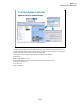
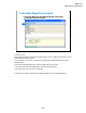
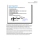
Connect 16493Q cables to make
synchronization of multiple SPGUs.
Max. 5 Modules (10 output channels)
LED to show the output switch status
(Master SPGU)
(Slave SPGU)
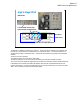
High Voltage SPGU
Rear View
PG1
PG2
PG3
PG4
Slot 1
Slot 2
The B1500A can install the maximum of five SPGUs. The SPGUs must be installed in the contiguous slots
from the slot 1. Where the SPGU installed in the slot 1 is the master SPGU. The channel number PG1 is
assigned for the Output 1 of the master SPGU. And the following numbers are assigned for the subsequent
channels.
The SPGU has seven connectors.
The Output connectors are for the SPGU signal output.
The Ref In/Out and Sync In/Out connectors are for making synchronization of multiple modules.
The Trig Out connector outputs the trigger signal used to make synchronization with the external instruments.
If the multiple SPGU modules are installed, the 16493Q cables must be connected between the Ref Out
connector and the Ref In connector and between the Sync Out connector and the Sync In connector as shown
above. This is necessary to synchronize the module outputs.