
Technical data


Module 13
SPGU Control and Applications
13-30
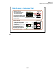
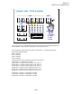
1: Substrate
2: Source
3: Gate
4: Drain
G
S
D
Sub
1
2
3 4
5
6
7
8
9
10
11
12
13
14 15
16
17
18
20
19
21
22
23
24
25
27
26
28
14
15
28
1
F
G
3
F
G
4
F
G
5
F
G
6
F
G
2
F
G
1
SMU
2
1
VMU
2
1
VSU
F
S
GNDU
F
2
F
1
PGU
Jumper Leads – MOS transistor
For all class exercises, you need the 28-pin dual in line socket which comes standard with the 4145
fixture (16058A) or the newer fixture (16442A/B). Either fixture works fine.
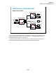
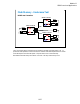
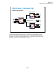
This class exercise requires four jumper leads to connect the DUT. Connect the jumper leads
between the following terminals.
SMU1 : terminal 1
SMU2 : terminal 2
SMU3 : terminal 3
SMU4 : terminal 4
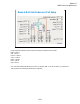
Then, the modules must be connected to the fixture as shown below.
B1500A SMU1 -> Fixture SMU1 connector
B1500A SMU2 -> Selector ch1 SMU input or ASU ch1 Force
B1500A SMU3 -> Selector ch2 SMU input or ASU ch2 Force
B1500A SMU4 -> Selector ch3 SMU input or ASU ch3 Force
B1500A PG2 -> Selector ch1 PGU input or ASU ch1 AUX In
B1500A PG3 -> Selector ch2 PGU input or ASU ch2 AUX In
B1500A PG4 -> Selector ch3 PGU input or ASU ch3 AUX In
Selector/ASU ch1 output -> Fixture SMU2 connector
Selector/ASU ch2 output -> Fixture SMU3 connector
Selector/ASU ch3 output -> Fixture SMU4 connector