
Technical data


Module 13
SPGU Control and Applications
13-27
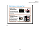
Flash Memory – Endurance Test
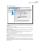
NOR Erase Connection
SMU3
Mech
Mech
Gate
Drain
Source
SMU1
Substrate
SMU4
PG4
Solid
State
Mech
Mech
SMU2
PG2
Solid
State
Mech
Mech
PG3
Selector or ASU ch2
Selector or ASU ch3
Selector or ASU ch1
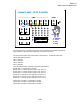
This is an example setup to perform the erase operation of the NOR type flash memory cell. To
perform the erase operation, all of the selector/ASU channels must make the path to the PG and the
PG3 internal pulse switch must be opened. The pulse switch is also a solid state relay.
Note that the solid state relay in the selector is not used. The relay must be always close.