Agilent B1500A Semiconductor Device Analyzer Self-paced Training Manual Agilent Technologies
Notices © Agilent Technologies 2005 - 2008 Manual Part Number No part of this manual may be reproduced in any form or by any means (including electronic storage and retrieval or translation into a foreign language) without prior agreement and written consent from Agilent Technologies, Inc. as governed by United States and international copyright laws.
In This Manual This document is the self-paced training manual to help you to understand what is Agilent B1500A, what functions the B1500A has, how to use the B1500A, and what applications the B1500A contributes to. CAUTION The test setup data described in this manual are only examples. If these example data damage your devices, Agilent is NOT LIABLE for the damage. • Module 1. Introduction This module explains the product concept and the key features of the B1500A/ EasyEXPERT.
• Module 11. Advanced Definitions and Operations This module explains how to control external GPIB devices, how to call an execution file, how to perform a repeat measurement, and how to use the prober control script. • Module 12. Miscellaneous Operations This module explains what is the status indicator, what is the automatic data export function and the automatic data record function, how to perform selftest and calibration, how to perform SMU zero offset cancel, and such. • Module 13.
Class Exercises Class exercises use the test setup listed below. The test setup data are only examples and included in the Demo.xpg file stored in the Manual CD-ROM.
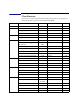
Module Exercise Device Test setup/definition/data Page Module 8 C-V sweep measurement MOSFET CV-1MHz 8-6 Module 9 Modifying application test definition MOSFET Trng IdVd Vth.xtd 9-14 Trng idvd idvg2.xtd 9-29 Trng idvd idvg3.xtd 9-32 Using auto analysys twice MOSFET Vth gmMax and Id 9-34 Using vector data MOSFET Trng Cgg-Vg 9-42 Module 10 Creating application test definition MOSFET Trng idvd idvg.
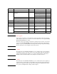
Test Setup for Class Exercises The Demo preset group contains the following test setup. The setup data are only examples for the class exercises. The following table lists the test setup name in alphabetical order. Test Setup Name Description ALWG monitor 511 kohm sampling measurement with SPGU ALWG output Charge Pumping 4T 0.
Test Setup Name Description Trng List MOSFET Vth-gmmax measurement using I/V List Sweep Trng Multi Multi Channel I/V Sweep (Bipolar transistor and LED) Trng Sampling 0.
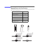
Required Devices for Class Exercises To perform the class exercises, you need the device set (Agilent part number 04156-87001) which contains the following devices. Description Quantity N-channel MOSFET 2 ea. NPN Bipolar Transistor 1 ea. Red Miniature LED 1 ea. 0.1 μF Capacitor 50 V 1 ea. 1.0 Ω Resistor 1/8 W 1 ea. 1.1 kΩ Resistor 1/8 W 1 ea. 511 kΩ Resistor 1/8 W 1 ea. N-ch MOSFET NPN bipolar Transistor LED Brown Black Black Silver 1 ohm Resistor Brown Brown Black Brown 1.
Required Accessories for Class Exercises To perform the class exercises, you need the following accessories. Prepare the accessories shown below. Designation 1 Description Test Fixture Model No. Qty. 16442A/B a 1 ea. 28 pin socket module 1 ea. Connection wire 6 ea. 2 Triaxial Cable 16494A 4 ea. 3 Interlock Cable 16493J 1 ea. 4 Kelvin Triaxial Cable, for Module 5 16493K 1 ea. 5 CMU Cable, for Module 8 N1300A 1 ea. 6 Atto Sense/Switch Unit, for Module 6 E5288A 1 ea.
To perform the flash memory class exercise in Module 13 and if you use the ASU, you need the following accessories. Description Model No. Qty. E5288A Total 3sets 16494A or equivalent Total 7ea. BNC-SMA Cable 16493P 3 ea. SMA-SMA Cable, for synchronization of SPGU 16493Q 2 ea. ASU (Atto Sense/Switch Unit) with control cable Triaxial Cable To perform the flash memory class exercise in Module 13 and if you use the selector, you need the following accessories. Description Model No. Qty.
Contents Module 1. Introduction • New Features • EasyEXPERT • To Perform Easy Application Test • User Interface • Modular Mainframe • SCUU/GSWU • ASU • SMU/Pulse Generator Selector • B2200/E5250 Switch Control • Desktop EasyEXPERT Module 2.
Contents Module 3. Data Display and Management • Data Display window • Graph Analysis Tools • Data Status • To Change Graph/List/Display Setup • To See Print Preview • To Print Display Data • To Copy Graph Plot/List Data • To Save Analysis Result • To Use Preview Window Module 4.
Contents Module 5. Basic Measurement • SMU Fundamentals • Classic Test Environment • SMUs Connected in Series or Parallel • Cabling and Fixture Issues • Kelvin and Driven Guard • Probes and Prober Connections • Triax and Coax Adapters • Safety Interlock Issues Module 6.
Contents Module 7. Measurement Functions • SMU Pulsed Sweep Measurement • I/V-t Sampling Measurement • Negative Hold Time for High Speed Sampling • Auto Analysis • SMU Filter • SMU Series Resistor • Standby Function • Bias Hold Function Module 8.
Contents Module 9. Modifying Application Test Definitions • To Open Application Test Definition • To Modify Test Definition • To Use Debug Tools • To Use Built-in Functions • To Add Data Display • To Use Auto Analysis • To Use Test Setup Internal Variables • To Use Auto Analysis twice (as Class Exercise) • To Use Vector Data (as Class Exercise) Module 10.
Contents Module 11. Advanced Definitions and Operations • To Control External GPIB Devices • To Call Execution Files • To Perform Repeat Measurements • Prober Control Script Module 12.
Contents Module 13.
Contents Contents-8
10 Creating Your Test Definitions
Module 10 Creating Your Test Definitions In This Module • What is Test Definition • What is Test Contents • To Open Test Definition Editor • To Define Test Specification • To Define Test Contents • Available Elements • Available Variables • To Define Test Output This section explains how to create your test definition. You will perform the above tasks to create the definition.
Module 10 Creating Your Test Definitions What is Test Definition Test Specification Test Output •Multi display mode •Variables •Analysis parameters •Test result display •X-Y graph •Data list •Parameter display •Test name •Test description •Variables •Device parameters •Test parameters •Entry fields Test Contents •Local variables •Test execution flow •Test setup •Classic test •Application test •My Favorite setup Test definition consists of test specification, test contents, and test output setup.
Module 10 Creating Your Test Definitions What is Test Contents Test Output Test Specification Variables •Device parameters •Test parameters Variables •Analysis parameters Analysis Local variables Miscellaneous Program Component Classic Test My Favorite Application Test Test contents are the test execution flow (program flow), and is the core of the test definition. In the test contents, the following elements can be defined.
Module 10 Creating Your Test Definitions To Open Test Definition Editor Define New Test… To start test definition, open the test definition editor. Select the Application Test tab, click the Library button, and select the Define New Test… function. The test definition editor will be opened. See next slide.
Module 10 Creating Your Test Definitions To Define Test Specification Set test information Define device parameters Set properties of parameter The test definition editor provides three tabs, Test Specification, Test Contents, and Test Output. At first define the test specification. Click the Test Specification tab. In the Test Information area: •Click the right button in the Category field to specify the category the new test definition belongs. •Enter the Test Name.
Module 10 Creating Your Test Definitions To Define Test Specification Set properties of parameter Define test parameters In the Test Parameters Definition area: •Select the Background that will be displayed on the application test setup area of the main screen. Usually it is the image that shows the device connections. •Set the Name, data type, Default value, and Description for the parameter. When you add a parameter, you will see the entry fields at the Properties area.
Module 10 Creating Your Test Definitions Setup example This example sets: Category: Exercise (This category may be created by the class exercise in Module 9) Test Name: Trng idvd idvg Icon: MOSFET.bmp Device parameters: Hold and Delay Background: Vth_Const_Id.
Module 10 Creating Your Test Definitions Setup example - Layout Primary Entry Field The Define Layout dialog box is used to define the layout of the test parameter entry fields displayed on the application test setup screen. The following methods are available for selecting the entry fields. •Click on the entry field. Multiple entry fields can be selected by clicking on the entry field while holding down the Ctrl key on the keyboard. •Drag the mouse to draw a rectangle around multiple entry fields.
Module 10 Creating Your Test Definitions Result example This is a result example of the test specification setup shown in the previous pages.
Module 10 Creating Your Test Definitions To Define Test Contents 4. Select available element 1 5. Click Insert or desired button 2. Define the local variables used in this test contents 3. Specify the line to insert element or to be edited 6. Define the setup required for the highlighted line (element) Starting to define the test contents: 1. Highlight the Local Variables Definition line. 2. Define the local variables used in this test contents (test execution flow). 3.
Module 10 Creating Your Test Definitions Available elements Program Component Application Test Analysis Classic Test Miscellaneous My Favorite Available elements are shown above. The Program Component provides the typical program statements such as IF, LOOP, FOR, and so on. They are used to control the test execution flow. The Application Test, Classic Test, and My Favorite are used to define the test setup/test condition.
Module 10 Creating Your Test Definitions Available variables Assign to external variables… Test Contents •Local variables Test Specification •Device parameters •Test parameters Test Output •Analysis parameters You can connect the variables in test setup with •Local variables •Device parameters •Test parameters •Analysis parameters Do not set the same name for variables and parameters. The name must be unique. In the test execution flow (program flow), you can use the following variables.
Module 10 Creating Your Test Definitions Defining local variables Local Variables Definition Add Numeric Variable button displays the Numeric Variable area that provides the following fields. •Name: Numeric variable name •Value: Initial value of the variable •Description: Additional information for the variable Add Vector Variable button displays the Vector Variable area that provides the following fields. •Name: Vector variable name. Two dimensional array.
Module 10 Creating Your Test Definitions Editing test contents •Block Selection •Insert •Delete •Copy •Cut •Paste The Edit tab provides the following buttons: •Block Selection/Line Selection toggle button selects the edit target selection mode. In the line selection mode, clicking line just selects the line. In the block selection mode, clicking line selects the block the line belongs. •Insert button inserts the specified element between the highlighted line and the next line.
Module 10 Creating Your Test Definitions Debug menu •Run •Abort •Stop •Break •Inspect The Debug tab menu provides the following buttons: •Run button starts the debug (executes the test flow). During execution, the label changes to Pause. Clicking Pause button pauses the execution, and changes the label to Run that is used to continue the debug (execution). •Abort button aborts the debug (execution). •Step button executes the highlighted line of the test flow.
Module 10 Creating Your Test Definitions Class Exercise Create test definition and perform test. 1. Open test definition editor. 2. Define Test Specification (see previous page) 3. Define Test Contents shown below. 4. Save the definition as Trng idvd idvg. 5. Use debug tools to check the definition. 6. Connect device, and perform test.
Module 10 Creating Your Test Definitions Test Definition Example variables Use IDVD and GMMAX in the Demo preset group (My Favorite Setup) for the test setup. Use the variables defined in the Test Specification to set the Unit on the Channel Setup, the source values on the Measurement Setup, the Min and Max values on the Display Setup, and so on. For the example definition, open the Trng idvd idvg definition stored in the \data folder on the Manual CD-ROM.
Module 10 Creating Your Test Definitions Measurement Result Example This is a test result example displayed on the Data Display window.
Module 10 Creating Your Test Definitions To Define Test Output 2. Define the analysis parameters 1 6. Select the multi display mode Comply with above level Enable Disable 3. Specify X axis and Y axis 4. Select variables to list 5. Select parameters to display The test output setup is optional. If you have the following requirements, define the analysis parameters and set the display parameters.
Module 10 Creating Your Test Definitions To Define Test Output Analysis Parameters Define Analysis Parameters… Define the analysis parameters as shown below: At the Vector Parameters area or the Scalar Parameters area: 1. Click the Add button. 2. Enter the Name, Unit, and Description of the parameter. For the sweep output/measurement data, use the vector parameter. For the spot output/measurement data, use the scalar parameter.
Module 10 Creating Your Test Definitions To Define Test Output Display Parameters This example sets: X-Y Graph: ID-VG plot for Y1-X graph and GM-VG plot for Y2-X graph List Display: VG, ID, and GM Parameters: GM_MAX and VTH All parameters must be defined in the Analysis Parameter Definition window shown in the previous slide. The X-Y Graph area is used to set the X axis and Y axis of the X-Y Graph Plot area on the Data Display window.
11 Advanced Definitions and Operations
Module 11 Advanced Definitions and Operations In This Module • To Control External GPIB Devices • To Call Execution Files • To Perform Repeat Measurements • Prober Control Script 11-2
Module 11 Advanced Definitions and Operations To Control External GPIB Devices Miscellaneous: GPIB I/O Write String to send a string command to GPIB device Write Value to send a command to GPIB device Read String to read a string value from GPIB device Read Value to read a numeric value data from GPIB device Read List to read a vector data from GPIB device Read STB to read status byte of GPIB device GP-IB Control Group Execution Trigger Device Clear Go To Local Local LockOut You can control ex
Module 11 Advanced Definitions and Operations To Control External GPIB Devices Agilent B2200 control example To send command Programming image: *RST :ROUT:FUNC ACON (enters “SMU1” to StringPort) :ROUT:SYMB:PORT {0},”{1}” :ROUT:SYMB:PORT? {0} (reads string data) *OPC? (reads operation complete flag) (enters “OUT1” to StringCh) :ROUT:SYMB:CHAN {0},{2},”{1}” :ROUT:SYMB:CHAN? {0},{2} (reads string data) *OPC? (reads operation complete flag) Value 1 Value 2 Value 3 Value 4 {0} {1} {2} {3} This slide shows a
Module 11 Advanced Definitions and Operations To Control External GPIB Devices Agilent B2200 control example To read data Programming image: *RST :ROUT:FUNC ACON (enters “SMU1” to StringPort) :ROUT:SYMB:PORT {0},”{1}” :ROUT:SYMB:PORT? {0} (reads string data) *OPC? (reads operation complete flag) (enters “OUT1” to StringCh) :ROUT:SYMB:CHAN {0},{2},”{1}” :ROUT:SYMB:CHAN? {0},{2} (reads string data) *OPC? (reads operation complete flag) This example uses the Read String function to read the response from th
Module 11 Advanced Definitions and Operations To Call Execution Files Miscellaneous: Command Execution Specifies vector variable or string sent to the exe file. Specifies variables used to receive execution results or output data. This area is deleted by Read Type: None. You can call the execution file (EXE file) from the EasyEXPERT. Use the Command Execution statement and define the setup editor as shown in this example.
Module 11 Advanced Definitions and Operations To set Format field {I[,A][:F]} • I List data index. Or index of element. Integer. • [,A] Character length of the specified data element. Positive integer for right-aligned, or negative integer for left-aligned. Optional. • [:F] Format identifier. C, D, E, F, G, N, P, R, or X. Lower case is available. Optional. Example: {0,5:E} First element, 5 characters, exponential notation. {1:G} Second element, general. {2,10} Third element, 10 characters, general.
Module 11 Advanced Definitions and Operations Exercise Try to improve your test definition as you want.
Module 11 Advanced Definitions and Operations To Perform Repeat Measurements Start (Run) Count=0 Start Procedure C:\Program Files\Agilent\B1500\EasyEXPERT status=True ? Yes No Count < limit C:\Program Files\Agilent\B1500\EasyEXPERT No Yes A C:\Program Files\Agilent\B1500\EasyEXPERT Test Execution Count=Count+1 Iteration Procedure No Abort 5 status=True ? Yes Final Procedure If Abort is clicked status limit End Repeat measurement is performed as shown in this flowchart.
Module 11 Advanced Definitions and Operations Subsite move Test Setup Save Specify ProberType. Or specify driver for your prober in CustomProber. Select If you do not use the sub die (subsite) move operation, skip this page. Click Application Test tab and open the Subsite move test setup in the Utility category. On the Subsite move setup screen, specify ProberType (Cascade, Suss, or Vector) or driver for your prober in CustomerProber, and save it as a setup in your preset group (My Favorite Setup).
Module 11 Advanced Definitions and Operations To Use Subsite move C:\Program Files\Agilent\B1500\EasyEXP C:\Program Files\Agilent\B1500\EasyEXP C:\Program Files\Agilent\B1500\EasyEXP 5 If you do not use the sub die (subsite) move operation, skip this page. To perform the test with the sub die move operation, do as follows. 1. Add the Subsite move test setup to your preset group (My Favorite setup). 2. Set your preset group and test setups in the Quick Test tab screen. 3.
Module 11 Advanced Definitions and Operations Prober Control Script • Prober information file Use prober control script in EasyEXPERT prober_info.ini Repeat Measurement Setup window • Start Procedure Start_xxxx.exe • Iteration Procedure Iterator_xxxx.exe • Final Procedure Final_xxxx.exe • Subsite Procedure Subsite_xxxx.exe xxxx: • cascade • suss • vector Prober control script is sample program used for semi-automatic prober control.
Module 11 Advanced Definitions and Operations Start_xxxx.exe • Arguments: Start -a GPIB_address -l log_file_name Displays Device ID Entry dialog box Example: –a GPIB0::5::INSTR –l C:\temp\prb.log • Response: Updates prober_info.
Module 11 Advanced Definitions and Operations Prober_info.ini [Prober] Address=GPIB::5::INSTR LogMode=True LogName=C:\temp\prb.log [Target] UseID=True SubsiteInfo=False WaferInfo=False ID=waf1a GPIB address of prober Full path name of log file device_id = prefix:coordinate False waf1a:4 1 Prefix you enter in the Device ID Entry dialog box. ID is automatically recorded in the prober_info.ini file.
Module 11 Advanced Definitions and Operations Iterator_xxxx.exe • Arguments: Start -a GPIB_address -l log_file_name Chuck down Example: –a GPIB0::5::INSTR –l C:\temp\prb.
Module 11 Advanced Definitions and Operations Final_xxxx.exe • Arguments: -a GPIB_address -l log_file_name Example: –a GPIB0::5::INSTR –l C:\temp\prb.log • Response: none C:\Program Files\Agilent\B1500\EasyEXP Start C:\Program Files\Agilent\B1500\EasyEXP Chuck down C:\Program Files\Agilent\B1500\EasyEXP End Stop condition 5 To specify the final procedure on the Repeat Measurement Setup dialog box, enter the full path name of Final_xxxx.exe into the Final Procedure field.
Module 11 Advanced Definitions and Operations Subsite_xxxx.exe • Arguments: Start -a GPIB_address -l log_file_name Chuck down Example: –a GPIB0::5::INSTR –l C:\temp\prb.
Module 11 Advanced Definitions and Operations To Change Execution Flow Test Execution A Subsite Procedure No B status=True ? Yes Move to the 1st subsite If you use the subsite procedure, change the flowchart as follows. On the page 11-9, replace the box A with the block A shown above. On the page 11-13 and 11-15, insert the box B shown above to the position B of the flowchart.
12 Miscellaneous Operations
Module 12 Miscellaneous Operations In This Module • Function Status Indicators • Run Option • Automatic Data Export and Data Record • Calibration • Configuration • XSLT Filters • To Enable System Controller • To Start Desktop EasyEXPERT • To Use 415x Setup File Converter This module describes the above topics.
Module 12 Miscellaneous Operations Function Status Indicators Automatic data record ON Automatic data export OFF SMU zero offset cancel OFF Standby function OFF Multiple data display OFF OFF ON ON ON ON Function status indicators let you know the status OFF or ON of the following functions. The indicators are placed at the bottom of the main screen. Multi Display OFF/ON: Shows the multiple data display function OFF or ON status. Standby OFF/ON: Shows the standby function OFF or ON status.
Module 12 Miscellaneous Operations Run Option Auto Export and Auto Record status: or or Save Data button appears if the last test result data is in the memory when both Auto Export and Auto Record are OFF, and allows you to save the last data as the test result record.
Module 12 Miscellaneous Operations Automatic Data Export and Data Record The automatic data export function and the automatic data record function can be enabled or disabled by using the Test Results Data Auto Export dialog box. This dialog box is displayed by clicking these indicators or selecting the Results > Transport Data > Auto Export Setting… menu. The automatic data export function is used to export the test result data automatically to the storage device you specify.
Module 12 Miscellaneous Operations Module Self Calibration Calibration The Calibration window is opened by clicking the Calibration button. The Module Self Calibration screen of this window is used to perform the calibration of SMUs. The list area of this screen lists Name, Full Range, and Status. Name: Name of module. To select, check the left check box. Full Range: For the high resolution SMU (HRSMU) connected to the atto sense/switch unit (ASU). Full range calibration on or off.
Module 12 Miscellaneous Operations SMU Zero Cancel Calibration 1 2 3 The SMU Zero Cancel screen is used to perform the SMU zero offset current measurement and set the SMU zero offset cancel function. This function subtracts the offset current from the current measurement raw data, and returns the result as the measurement data. This function is used to compensate the error factor (offset current) caused by the measurement path such as the measurement cables, manipulators, or probe card.
Module 12 Miscellaneous Operations CMU Calibration Calibration The CMU Calibration screen is used to perform the measurement data correction of the multi frequency capacitance measurement unit (MFCMU). For the easy way, perform the phase compensation and the open correction at least. The check boxes left of the Open/Short/Load Correction and the Phase Compensation are effective after the corresponding measurement is performed.
Module 12 Miscellaneous Operations Advanced Options for CMU Calibration This dialog box is opened by clicking the Advanced Options... button, and is used to set the information required to measure the open/short/load correction data and the phase compensation data. This dialog box provides the following action button. OK: Applies the setup changes and closes this dialog box. Cancel: Cancel the setup changes and closes this dialog box.
Module 12 Miscellaneous Operations Advanced Options for CMU Calibration Integration Time area defines the integration time used for measuring phase compensation data or open/short/load correction data. The number of averaging samples (Mode=AUTO) or the averaging time (Mode=PLC) is set. Mode: A/D converter operation mode, AUTO or PLC. Factor: Factor for the initial value. For details, see online help or user’s guide.
Module 12 Miscellaneous Operations Advanced Options for CMU Calibration Reference Standard Values area provides the following entry fields used to set the reference values of the open/short/load standard. If you use the standard, enter the reference values to the entry fields. OPEN Reference: Capacitance and Conductance. If you do not use the reference, enter 0 in the both fields. SHORT Reference: Inductance and Resistance. If you do not use the reference, enter 0 in the both fields.
Module 12 Miscellaneous Operations Configuration Main Frame The Configuration window is opened by clicking the Configuration button, and is used to display the system information and event log, as well as to perform diagnostics and self-test. The Main Frame screen is used to display the system information and perform diagnostics. Model Identification: Displays the instrument ID. B1500A. Line Frequency: Sets the power line frequency, 50 Hz or 60 Hz. EasyEXPERT Rev.
Module 12 Miscellaneous Operations Configuration Modules The Modules screen is used to perform self-test of modules. Slot: Slot number where the module is installed. To select, check the left check box. Module Type: Module model number Name: Module name Status: Self-test status, Passed, Failed, Recovered, or ---- (self-test has not been performed) SCUU: Specifies if the module is connected to the SCUU. Notes: Error information when the module self-test failed.
Module 12 Miscellaneous Operations Configuration ASU The ASU screen is available if the B1500A installs the HRSMU connected to the ASU (Atto Sense/Switch Unit), and shows the ASU information. Slot: Slot number Module Type: Type of module Name: Module name or SMU name ASU Serial Number: Serial number of the ASU registered as a pair with the HRSMU. This cell displays an error message instead of the serial number if unpaired ASU is connected.
Module 12 Miscellaneous Operations Configuration Switching Matrix The Switching Matrix screen is used to establish the GPIB connection with Agilent B2200A/B2201A/E5250A switching matrix and define the B2200A/B2201A/E5250A input port connections. Switching Matrix Type: Displays the type of the switching matrix or No Switching Matrix. GPIB Address: Specifies the GPIB address of the switching matrix. 1 to 30. Poll: Confirms if the switching matrix of the specified GPIB address is connected to the B1500A.
Module 12 Miscellaneous Operations Extended Configuration Configuration This dialog box is opened by clicking the Extended Configuration button in the Configuration window Switching Matrix screen. Save as Hardware Profile is used to save the hardware profile that is the B2200A/B2201A/E5250A hardware configuration and the measurement module connection. Click the Save button to save the present hardware profile. The hardware profile can be made for each workspace individually.
Module 12 Miscellaneous Operations Configuration SMU/PG Selector The SMU/PG Selector screen is used to specify the input connection and the channel connection status of the Agilent 16440A SMU/PG selector. Enable SMU/PG Selector: Check this box to use the selector. Selector CH1/CH2: Indicates the channels 1 and 2 of the first selector respectively. Selector CH3/CH4: Indicates the channels 1 and 2 of the second selector respectively.
Module 12 Miscellaneous Operations SMU/PG Selector ● Easy to switch between SMU and PGU ● Solid state relay 16440A Selector Input SMU Channel 1 SW1 Input PGU SW3 Channel 2 Input SMU To DUT SW2 SW1 Input PGU To DUT SW2 SW1 & SW2 : Mechanical Relay ✓ Flash Memory Test photomos SW3: Solid State Relay ✓ Transistor The selector has two channels as shown above. Each channel has two ports (SMU and PGU). External pulse generators can also be connected.
Module 12 Miscellaneous Operations Configuration Event Log The Event Log screen displays the event log. Date/Time: Displays date and time of the event. Message: Event message ID: Process ID of the event Process: Process name User: User name. Windows login name. Host: Host name of the B1500 The Refresh button refreshes the event log.
Module 12 Miscellaneous Operations XSLT Filters Click this button Highlight this line The XSLT (XSL-Transformation, eXtensible Stylesheet Language Transformation) filter files are used to export test records. The fifteen filter files listed below are stored in the C:\Program Files\Agilent\B1500\EasyEXPERT\Utilities\XSLT folder. The following filter files are used for exporting the measurement data only. meas-csv.xsl, meas-tab-sv.xsl, meas-xmlss.
Module 12 Miscellaneous Operations To Enable System Controller Agilent IO Library Connection Expert To control external GPIB devices, the B1500A must be set to system controller. Exit the EasyEXPERT, and close the Start EasyEXPERT window. After that, launch the Agilent Connection Expert by clicking Start, All Programs, Agilent IO Library Suite, and Agilent connection Expert. On the Agilent Connection Expert, change the GPIB configuration of the B1500A. •Select GPIB0. •Click Change Properties… button.
Module 12 Miscellaneous Operations To Start Desktop EasyEXPERT Database Backup Creation Wizard Database Restoration Wizard Important: To set the same configuration as the B1500A, copy the following file from B1500A to your PC. The location must be the same. \Documents and Settings\All Users\Application Data\Agilent Technologies, Inc\EasyEXPERT\UnitConfigB1500A.xml To open the Start EasyEXPERT window, click Start > Programs > Start EasyEXPERT menu.
Module 12 Miscellaneous Operations To Use 415x Setup File Converter Import 4155/4156 setup file (file extension: MES or DAT) EasyEXPERT setup file (file extension: XTS) SetupFileConverter.exe Execution example: C:\Mydata>SetupFileConverter.exe setup1.dat C:\Mydata>SetupFileConverter.exe *.mes You can reuse the 4155/4156 setup file (MES file or DAT file) for the test using EasyEXPERT.
Module 12 Miscellaneous Operations To Use 415x Setup File Converter 1. Drag and drop the shortcuts of the MES/DAT file on the shortcut of the Setup File Converter. 3. XTS file and shortcut are created. 2. File conversion is executed and system message is displayed. You can perform the file conversion on the Windows desktop as follows. 1. Create a shortcut of the SetupFileConverter.exe on the desktop. 2. Copy your MES/DAT files to the desktop. 3.
Module 12 Miscellaneous Operations To Use 415x Setup File Converter Click [Start] → All Programs → Agilent B1500A EasyEXPERT → 4155,4156 Setup File Converter To create XTS file: The following procedure converts the 4155/4156 setup file (.DAT or .MES) and creates the .XTS file in the folder the setup file is stored. 1. Click Select icon, or click File > Select Files to open the Select 4155/4156 MES Files or DAT Files dialog box. 2. Specify the 4155/4156 setup files to convert.
Module 12 Miscellaneous Operations 12-26
13 SPGU Control and Applications
Module 13 SPGU Control and Applications In This Module • High Voltage SPGU • SPGU Control • Pulse Generator Mode • Charge Pumping • Flash Memory Test • ALWG Mode 13-2
Module 13 SPGU Control and Applications High Voltage SPGU High Voltage Semiconductor Pulse Generator Unit z z z z z z z z 2 channels per module Output impedance: 50 ohm Amplitude: +/-40 V (open load), +/-20 V (50 ohm load) PG mode or ALWG mode Free run, duration, or count 2- or 3-level pulse output for each channel in PG mode Pulse switch Automatic voltage level adjustment 50 ohm Pulse switch 3-level voltage pulse ALWG voltage SPGU OUT ✓ Charge Pumping Memory Test ✓ AC Stress ✓ Flash High Voltage Se
Module 13 SPGU Control and Applications High Voltage SPGU Rear View Connect 16493Q cables to make synchronization of multiple SPGUs. Max. 5 Modules (10 output channels) PG3 PG4 PG1 PG2 Slot 2 (Slave SPGU) Slot 1 (Master SPGU) LED to show the output switch status The B1500A can install the maximum of five SPGUs. The SPGUs must be installed in the contiguous slots from the slot 1. Where the SPGU installed in the slot 1 is the master SPGU.
Module 13 SPGU Control and Applications High Voltage SPGU Pulse Switch CLOSE Write Erase Drain CLOSE Substrate Gate OPEN SMU Source Drain SMU CLOSE Pulse period Substrate Gate OPEN SMU Source SMU Write Erase The pulse switch is the built-in high speed analog switch to open/close the SPGU output for each channel. This switch is used in the write/erase cycle of the NOR type flash memory cell test.
Module 13 SPGU Control and Applications High Voltage SPGU Effects of Load Impedance Output Impedance 50 Ω Vset V Pulse Source Vdut Rdut Vset: Setting voltage with open load Vdut = Vset × Rdut Rdut + 50 The voltage actually applied to the DUT depends on it’s impedance. This behavior is very common among the instrumentations like DC power supply and pulse generators.
Module 13 SPGU Control and Applications High Voltage SPGU Effects of Load Impedance Mismatch of load impedance setting may cause the error of applied voltage to the DUT. Actual Expected Setup: 1V output, 50 Ω load Actual load: 1 MΩ Æ 2 V output Expected Actual Setup: 1 V output, 1 MΩ load Actual load: 50 Ω Æ 0.5 V output Here is the example of the voltage error due to the mismatch of the load impedance setting.
Module 13 SPGU Control and Applications High Voltage SPGU Agilent 16493P BNC (m) - SMA (m) Cable BNC (m) connector: • To connector plate • To 16442A/B test fixture • To 16440A SMU/PGU selector • To E5288A ASU (Atto Sense and Switch Unit ) SMA (m) connector: • To SPGU output Agilent 16493P is the connection cable for the SPGU outputs.
Module 13 SPGU Control and Applications SPGU Control Mode: VPULSE or ALWG Check here to display the Percent of Progress vs. Time plot. Check here to display the Time data list. The SPGU can be used in the classic test other than the C-V Sweep and the Switching Matrix Control. So you can use the SPGU output while a measurement is performed. If you need the SPGU output only, use the SPGU Control classic test.
Module 13 SPGU Control and Applications SPGU Control SPGU Pulse Setup SPGU Control Buttons on Measurement Setup screen of a Classic Test If the SPGU output mode is set to VPULSE, the Pulse/ALWG button opens the SPGU Pulse Setup window. This window is used to define the voltage pulses applied by the specified SPGU channels. For the setup parameters, see later page titled Pulse Setup Parameters of Pulse Generator Mode.
Module 13 SPGU Control and Applications SPGU Control Pulse Switch Setup 50 ohm Pulse period Pulse switch SPGU OUT Delay Width 3-level voltage pulse Write OPEN Erase Default setting of the switch is “CLOSE” You can set the pulse switch operation on the Pulse Switch Setup dialog box. Set the SW Sync to ENABLE to use the pulse switch. The delay time is the time from start of pulse output to changeover of pulse switch. The width is the duration to hold the switched state of the pulse switch.
Module 13 SPGU Control and Applications SPGU Control Load Z Setup Output Impedance Setting (default=50 ohm) 50 Ω Vset V Vdut Rdut Vset: Setting voltage with open load You can specify the load impedance of DUT on the Load Z Setup dialog box. By setting the load impedance value accurately, the SPGU can apply the voltage near the setting value to the DUT.
Module 13 SPGU Control and Applications SPGU Control SPGU ALWG Setup SPGU Control Buttons on Measurement Setup screen of a Classic Test This button opens the Define ALWG Waveform window used to define the ALWG output sequence. If the SPGU output mode is set to ALWG, the Pulse/ALWG button opens the SPGU ALWG Setup window. This window is used to define the arbitrary linear waveform voltage applied by the specified SPGU channels.
Module 13 SPGU Control and Applications Pulse Generator Mode Pulse Setup Parameters Pulse period Pulse width Leading time Trailing time Pulse peak 90 % Amplitude 10 % Pulse base Delay time The pulse setup parameters are defined as shown above. The pulse leading time and trailing time are defined as the voltage transition time between 10 % and 90 % of the amplitude. Minimum setting value is 8 ns.
Module 13 SPGU Control and Applications Pulse Generator Mode Pulse output example: 2. SPGU Pulse Setup window Pulse period 3. Pulse setup parameters To apply the SPGU pulse output, set the pulse setup parameters, specify the Operation, and click the Single button. The following operations are available. PULSE COUNT: SPGU outputs the specified number of pulses. Specify a number within the range of 1 to 1000000. DURATION: SPGU continues the output until the specified time elapses.
Module 13 SPGU Control and Applications Pulse Generator Mode 3-Level Pulses • Every channel can output 3-level pulse 80 Vp-p within +/-40 V window (at open load) • Pulse width and level of each channel can be set individually. SPGU10 +40V 80Vpp SPGU3 SPGU2 -40V SPGU1 Up to 10 output channels can be installed in one B1500A and each channel can output 3-level pulse with a maximum output voltage. The channels are independent. So the channels can apply the different pulses.
Module 13 SPGU Control and Applications Charge Pumping Gate Source n+ Drain Oxide n+ p or A Substrate A SMU PGU Icp SMU Charge pumping is a type of hot carrier measurement. It provides direct measurement of interface states and an indication of electron and hole trapping. The gate of the MOS transistor is connected to a pulse generator. The current (Icp) is caused by the repetitive recombination of minority carriers with majority carriers at the silicon-silicon oxide interface.
Module 13 SPGU Control and Applications Charge Pumping Three Methods of Charge Pumping Gate Waveforms Voltage Square Pulse Triangle Pulse Trapezoidal Pulse Time Square Pulse The base of the pulse is stepped from well below gate threshold to well above. At each step, the substrate leakage current is monitored. The flat part of the resultant curve is proportional to interface-state density. Triangle Pulse The frequency of a constant height triangle pulse is increased in steps.
Module 13 SPGU Control and Applications Charge Pumping Start Calculates Vbase & Sets meas. parameters to I_sub sampling test I_sub sampling meas. by applying Vg pulse Records Isub and Vbase More Vbase? Y Looping of classic test for each base step of Gate pulse. N Calculates IcpMax & NSS Plots Icp vs Vbase Icp is measured after each increment of the gate pulse base value. A curve of Icp vs base value is plotted. The maximum Icp value is noted.
Module 13 SPGU Control and Applications Class Exercise Square Pulse Charge Pumping 1. Recall the Charge Pumping 4T 0.1V step test record. 2. Connect the DUT (MOS FET) as shown in the next page. 3. Specify the module (SMU and PGU) connected to DUT terminal properly. 4. Perform the test.
Module 13 SPGU Control and Applications Jumper Leads – MOS transistor F 1 F G F 2 PGU F PG1 1 1 VSU VMU SMU F 4 G G G 1 F 3 F 5 F G GNDU 6 F S G 2 2 2 1 2 3 4 5 6 7 8 9 10 11 12 13 14 15 16 17 18 19 20 21 22 23 24 28 15 25 26 27 28 14 1 S D G Sub 1: Substrate 2: Source 3: Gate 4: Drain For all class exercises, you need the 28-pin dual in line socket which comes standard with the 4145 fixture (16058A) or the newer fixture (16442A/B).
Module 13 SPGU Control and Applications Measurement Result Example Here we see the result of plotting Icp vs pulse base voltage.
Module 13 SPGU Control and Applications Flash Memory Basic Flash memory Cell Structure VCG Control gate Id Write Erase (discharged) (Qf is injected) Floating node Vd C2 C3 Qf C0 Delta Vg C1 Source Drain VCG Voltage for Write/Erase judgment Bulk Qf is injected (by a pulse) to write the memory Effective gate voltage shifts Delta Vg = Qf/Cf. Cf is effective floating gate capacitance. Flash memory is one type of floating gate memory.
Module 13 SPGU Control and Applications Flash Memory – Endurance Test 1 million Write/Erase cycle test Start Initial Write/Erase Test Next burst test End Vth (V) T i <= 10^6 F Burst Write/Erase Test Write/ Program Write Measure Vth (*1) Erase Measure Vth (*2) Erase (*1) Id(on) and Id(off) are measured as well. (*2) Id(on), Id(off) and sub-threshold swing (Sfactor) are measured as well. 0 10 1 10 2 10 3 4 10 10 Cycles 5 10 6 10 Endurance test is a kind of reliability tests.
Module 13 SPGU Control and Applications Flash Memory – Endurance Test NAND Cell Test • Burst write/erase reduces test time dramatically Write pulse SPGU output Gate 40V Drain -40V In an example, the test time was less Source than 2 hours for 1 million cycle test. Sub It will be about 1/70 compared with 3-level pulse by each channel Erase pulse 4155/4156 solution. Write pulses Open NOR Cell Test • Drain open can be made by opening the analog switch in the HVSPGU.
Module 13 SPGU Control and Applications Flash Memory – Endurance Test NOR Write Connection Selector or ASU ch3 Mech Solid Mech State Selector or ASU ch2 SMU3 Drain Mech Mech Gate Source PG4 SMU1 Substrate PG3 SMU4 Selector or ASU ch1 Mech Solid Mech State SMU2 PG2 This is an example setup to perform the write operation of the NOR type flash memory cell. This setup uses three sets of the SMU, SPGU, and selector/ASU.
Module 13 SPGU Control and Applications Flash Memory – Endurance Test NOR Erase Connection Selector or ASU ch3 Mech Solid Mech State Selector or ASU ch2 SMU3 Drain Mech Mech Gate Source PG4 SMU1 Substrate PG3 SMU4 Selector or ASU ch1 Mech Solid Mech State SMU2 PG2 This is an example setup to perform the erase operation of the NOR type flash memory cell.
Module 13 SPGU Control and Applications Flash Memory – Endurance Test Measure Vth Connection Selector or ASU ch3 Mech Solid Mech State Selector or ASU ch2 SMU3 Drain Mech Mech Gate Source PG4 SMU1 Substrate PG3 SMU4 Selector or ASU ch1 Mech Solid Mech State SMU2 PG2 Vth must be measured after writing or erasing. To perform the Vth measurement, all of the selector/ASU channels must make the path to the SMU.
Module 13 SPGU Control and Applications Class Exercise Flash Memory Endurance Test 1. Recall the Demo-S-NorFlash Endurance test record. 2. Connect the DUT (MOS FET, not flash memory) as shown in the next page. 3. Specify the module (SMU and PGU) connected to DUT terminal properly. 4. Perform the test. To perform this class exercise, you need the following equipment.
Module 13 SPGU Control and Applications Jumper Leads – MOS transistor F 1 F G F 2 1 1 PGU F VSU VMU SMU F 4 G G G 1 F 3 F 5 F G GNDU 6 F S G 2 2 2 1 2 3 4 5 6 7 8 9 10 11 12 13 14 15 16 17 18 19 20 21 22 23 24 28 15 25 26 27 28 14 1 S D G Sub 1: Substrate 2: Source 3: Gate 4: Drain For all class exercises, you need the 28-pin dual in line socket which comes standard with the 4145 fixture (16058A) or the newer fixture (16442A/B).
Module 13 SPGU Control and Applications Demo-S-NorFlash Endurance Test Setup For the instrument connection shown in the previous pages, change the value as follows. Pgate -> SPGU3 Gate -> SMU3 Psource -> SPGU2 Source -> SMU2 Pdrain -> SPGU4 Drain -> SMU4 Subs -> SMU1 Also, set a small TotalWriteAndEraseCycles value, for example 1000. If you set one million, you will have to wait long time over several hours until the test is completed.
Module 13 SPGU Control and Applications Measurement Result Example Write Erase This is a test result example displayed on the Data Display window.
Module 13 SPGU Control and Applications ALWG Mode Specify number of repeat for each pattern group. 50 ns 50 ns PG1 Output Pattern 1 Pattern 2 Pattern N Smooth Transition! No Glitch , No dip to GND. Δt PG2 Output Pattern 3 Pattern 4 Pattern X Must be < (1,024 - # of Patterns) points for each channel ALWG stands for Arbitrary Linear Waveform Generator. This function is similar to the AWG (Arbitrary Waveform Generator), but specialized for a semiconductor parametric test.
Module 13 SPGU Control and Applications ALWG Mode 1. SPGU ALWG Setup Window Count Pattern Open This button opens the Pattern Editor used to define the arbitrary linear waveform. 2. Define ALWG Waveform window To apply the ALWG output, define the ALWG output sequence, specify the Operation, and click the Single button. The following operations are available. PULSE COUNT: SPGU outputs the specified number of sequences. Specify a number within the range of 1 to 1000000.
Module 13 SPGU Control and Applications ALWG Mode A pattern can be defined by specifying the differential time and the absolute voltage. You can define it by using the left side GUI or the right side table on the window.
Module 13 SPGU Control and Applications Class Exercise Monitor ALWG output by the sampling measurement. 1. Click I/V-t Sampling icon and open setup editor. 2. Define the measurement setup with the ALWG output. 3. Save the test setup. 4. Connect a device (511 kohm resistor) as shown in the next page. 5. Perform the test.
Module 13 SPGU Control and Applications Jumper Leads – Capacitance F 1 F G 2 PGU F PG1 1 1 F VSU VMU SMU F 4 G G G 1 F 3 F 5 F G GNDU 6 F S G 2 2 2 4 5 6 9 10 11 12 14 15 16 17 18 20 21 22 23 1 2 7 8 13 19 28 3 15 24 25 26 27 28 14 1 511 kohm For all class exercises, you need the 28-pin dual in line socket which comes standard with the 4145 fixture (16058A) or the newer fixture (16442A/B). Either fixture works fine.
Module 13 SPGU Control and Applications Measurement Result Example This is a test result example displayed on the Data Display window for the “ALWG monitor” test setup.