
Technical data


Agilent 41000 Administration Guide, Edition 3 3- 27
Using Agilent iPACE Verification Tool
Using Batch Mode
Connection Check
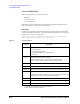
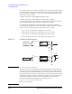
To perform the connection check in the batch mode, the connection check fixture
(E3143-60001) must be connected to the Agilent B2220A probe card interface. The fixture
has four 12 pin block, and the pins are connected by the resistor as shown in
Figure 3-13.
For the 48(24) pin configuration, the batch file should be created upon the following
connections of the voltage source (VS) and the voltmeter (VM).
• VS to 12(12), and VM to 1 through 11 (2 through 10)
• VS to 24(24), and VM to 13 through 23 (14 through 22)
• VS to 36(36), and VM to 25 through 35 (26 through 34)
• VS to 48(48), and VM to 37 through 47 (38 through 46)
Figure 3-13 E3143-60001 Internal Circuit and Voltage Source/Voltmeter Connection (non-Kelvin)
NOTE DC Voltage Measurement Result
Without any system error, the measurement result (Vmeas) should be almost equal to the
Vcalc value given by the following formula. Then n is an integer of 1 to 11 that means the
number of resistors between the measurement pin and the ground.
Vcalc = 10 × n / 12 (V)
For the 24 pin configuration, Vcalc = 10 × n / 6 (V). Then n is an even number of 2 to 10.
608)RUFH
9ROWDJHVRXUFH
608)RUFH
5
5
5
5
5
5
5
5
5
5
5
5
5
5
5
5
5
5
5
5
5
5
5
5
5
5
5
5
5
5
5
5
5
5
5
5
5
5
5
5
5
5
5
5
5
5
5
5
9
9PHDV