
Technical data


Agilent 41000 Administration Guide, Edition 3 3- 17
Using Agilent iPACE Verification Tool
Noise Offset Measurement
Execution Procedure
Perform the following procedure after the instrument self-test is completed as shown in
“Self-test” on page 3-9.
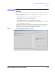
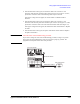
1. On the ‘iPACE Verification Tool’ window, click the ‘Verification’ tab, and select
Noise from the Test Item combo box. See
Figure 3-7.
2. Specify the voltage source by using Source.
The example in Figure 3-7 selects the SMU3.
3. Specify the switching matrix input port by using Input Port.
The example in Figure 3-7 selects the input port 3.
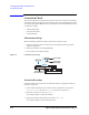
4. Specify the switching matrix output port by using Output Slot and Output Ch.
The example in Figure 3-7 selects the output port 3 of the switch module installed in
the slot number 3.
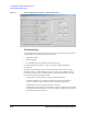
5. Click Run. A dialog box opens to prompt you for the measurement setup and the start
of the noise offset measurement.
Click Cancel to cancel the measurement, or click OK to start.
Clicking Break aborts the noise offset measurement and initializes the instruments.
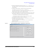
The result will be displayed on the ‘Report Window’ area. The result will be also
logged into the log file.
Wait until a dialog box opens to notify the measurement completion. Then click OK.
6. Repeat step 2 through 5 for the measurement paths you want to measure.
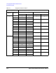
NOTE Measurement condition
Noise offset measurement condition is as follows.
Measurement mode Spot measurement
Number of measurement points 50
Output voltage 0 V
Measurement range Auto
Integration time 50 PLC
Wait time 10 sec.
The SMU specified in the Source combo box will measure current in this condition.
NOTE About measurement result data
IOffset value is given as the average of all measured current.
Noise value is given as the standard deviation value of all measured current.