
Technical data


3- 16 Agilent 41000 Administration Guide, Edition 3
Using Agilent iPACE Verification Tool
Noise Offset Measurement
Noise Offset Measurement
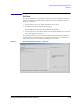
This section explains how to perform the noise offset measurement. The noise offset
measurement will be performed by applying 0 V from the DC source/monitor and
monitoring current by the DC source/monitor when the Agilent B2220A outputs are open.
• “Measurement Setup”
• “Execution Procedure”
• “Troubleshooting”
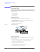
Measurement Setup
Make the following measurement setup to perform the noise offset measurement.
1. If you perform the measurement at the tip of the Agilent B2220A output pins:
Attach the E3190-60042 PV Open Fixture to the Agilent E3140A Test Fixture Adapter.
See
Figure 3-6.
2. If you perform the measurement at the tip of the probe card:
Attach the probe card to the E3144-60001 card fixture. Then attach the fixture with the
probe card to the Agilent E3140A Test Fixture Adapter. See
Figure 3-6.
3. Mount the test fixture on the Agilent B2220A.
4. Connect the interlock cable between the DC source/monitor and the Agilent B2220A.
5. Close the lid of the test fixture adapter.
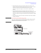
Figure 3-6 Noise Offset Measurement Setup
3UREHU
$JLOHQW%$
$JLOHQW($
(RU
(
$JLOHQW($
3UREH&DUG,QWHUIDFH