
Technical data


Agilent 41000 Administration Guide, Edition 3 3- 15
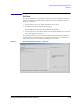
Using Agilent iPACE Verification Tool
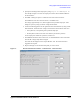
Connection Check
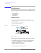
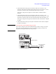
4. If the measurement result is good, reconnect the cable to the connector 2. And
disconnect cable from the switching matrix output connector (3 in
Figure 3-5). Then,
perform the connection check at the switching matrix output connector.
If the proper voltage does not appear, the switch module or mainframe will be
defective.
5. If the measurement result is good, reconnect the cable to the connector 3. And
disconnect cable from the probe card interface input connector (4 in
Figure 3-5). Then,
perform the connection check at the end of the measurement cable (B in Figure 3-5).
If the proper voltage does not appear, the measurement cable will be defective. Replace
the cable.
6. If the measurement result is good, the probe card interface will be defective. Replace
the probe card interface.
NOTE About the order of the troubleshooting procedure
If you want to change the order of the troubleshooting procedure, arrange it as you like.
Then, ignore the second paragraph in each step. You have to judge by yourself. The
judgement result depends on the order of the procedure.
'&VRXUFHPRQLWRU
0HDVXUHPHQWFDEOH$
6ZLWFKLQJPDWUL[
3UREHFDUGLQWHUIDFH
0HDVXUHPHQWFDEOH%