
Technical data


Agilent 41000 Administration Guide, Edition 3 3- 11
Using Agilent iPACE Verification Tool
Connection Check
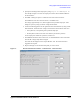
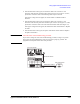
4. Specify the switching matrix output port by using Output Slot and Output Ch.
The example in Figure 3-4 selects the output port 2 of the switch module installed in
the slot number 2.
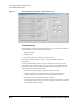
5. Click Run. A dialog box opens to confirm the start of the connection check.
Click Cancel to cancel the connection check, or click OK to start.
DC voltage (approximately 10 V) will be applied to the specified output port. And a
dialog box opens to prompt you for DC voltage measurement.
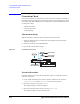
6. Contact the following patterns on the Agilent E3141A universal fixture by using a hand
held multimeter, and measure DC voltage. The measured value should be about 10 V.
• Force pattern (F) corresponding to the specified output port
• Ground pattern (inside circle of the circle drawn by the 48 force patterns)
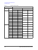
For the output ports and the force patterns, see Table 3-2.
7. Click OK if the measured value is about 10 V, or click Cancel if the value is abnormal.
Then the DC voltage output will be stopped.
The result will be displayed on the ‘Report Window’ area. The result will be also
logged into the log file.
8. Repeat 2 through 7 for the measurement paths you want to check.
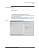
Figure 3-4 iPACE Verification Tool window - Verification tab - Connection Path