
Technical data


3- 10 Agilent 41000 Administration Guide, Edition 3
Using Agilent iPACE Verification Tool
Connection Check
Connection Check
This section explains how to perform the connection check. The connection check will be
performed by applying voltage from an instrument (voltage source) and monitoring voltage
at an output of the Agilent B2220A Probe Card Interface. A hand held multimeter is used
to measure the voltage.
• “Measurement Setup”
• “Execution Procedure”
• “Troubleshooting”
Measurement Setup
Make the following measurement setup to perform the connection check.
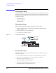
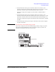
1. Attach the Agilent E3141A Universal Fixture to the Agilent E3140A Test Fixture
Adapter. See
Figure 3-3.
2. Mount the test fixture on the Agilent B2220A.
3. Open the lid of the test fixture adapter.
Figure 3-3 Connection Check Setup
Execution Procedure
Perform the following procedure after the instrument self-test is completed as shown in
“Self-test” on page 3-9.
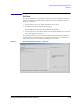
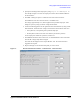
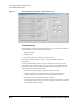
1. On the ‘iPACE Verification Tool’ window, click the ‘Verification’ tab, and select
Connection Path from the Test Item combo box. See
Figure 3-4.
2. Specify the voltage source by using Source.
The example in Figure 3-4 selects the SMU2.
3. Specify the switching matrix input port by using Input Port.
The example in Figure 3-4 selects the input port 2.
3UREHU
$JLOHQW%$
$JLOHQW($
(
$JLOHQW($
3UREH&DUG,QWHUIDFH