
Technical data


Agilent 41000 Administration Guide, Edition 3 2- 19
Installation and Operation
Installation
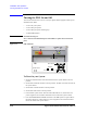
Model 300/400: To Connect Measurement Cables
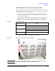
Connect measurement cables between the Agilent B2200 switch mainframe outputs and
the Agilent B2220A probe card interface inputs as shown below. For the cable connection
between instruments, see
“Service” on page 7-1.
1. Connect the interlock cable between the Agilent 4155C/4156C/E5270B’s interlock
connector and the interlock connector of the Agilent B2220A probe card interface.
See
Figure 2-11 and Figure 2-12.
2. Connect measurement cables between the Agilent B2200 outputs and the Agilent
B2220A inputs. Then, use the triaxial cables if there is no Kelvin connection in the
B2200 input, or else use the Kelvin triaxial cables. See
Figure 2-12 and Table 2-10.
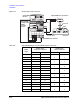
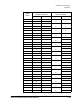
Table 2-9 Measurement Cables
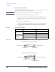
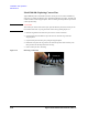
Figure 2-11 Interlock Cable Connection on Agilent B2220A
WARNING To prevent electrical shock during use, connect the interlock cable between the
interlock connector and the instrument’s interlock connector.
B2220A connector Cable
Input 1 to 48
(for
48 pin option)
Agilent 16494A triaxial cable for non-Kelvin connection
Agilent 16494C Kelvin triaxial cable for Kelvin connection
Input 2 to 48
1
(for 24 pin option)
1. There is no odd numbered connectors on the Agilent B2220A 24 pin option.
Only the even numbers are available for the 24 pin option.
Agilent 16494A triaxial cable for non-Kelvin connection
Agilent 16494C Kelvin triaxial cable for Kelvin connection
Interlock Agilent 16493J interlock cable