
Technical data


2- 18 Agilent 41000 Administration Guide, Edition 3
Installation and Operation
Installation
Model 300/400: To Use Test Fixture
If you perform the measurement of the package devices, use the test fixture. Then, install
the Agilent B2220A as standalone, not on the prober.
Preparation
1. Prepare the following items.
• Rubber feet, 4 ea. and bond or double-sided adhesive tape
The rubber feet should be attached on the corner of the B2220A top cover to protect
the jutty on the top cover.
• Agilent E3140A Test Fixture Adapter, 1 ea.
• Agilent E3141A Universal Test Fixture, 1 ea.
• Socket(s) for your devices
• Wire needed to connect between the E3141A’s soldering terminals and the socket
terminals
• Solder, soldering bit, and so on
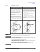
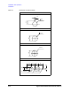
2. Design your test fixture and assemble it as show below.
a. Put the socket(s) on the top side of the E3141A universal test fixture, and fix it.
Then the device contacts must face up.
b. On the E3141A back side, place a wire between the E3141A’s soldering terminal
and the socket’s terminal, and solder it.
c. Repeat b as you designed.
Procedure
The following procedure shows how to install the Agilent B2220A. Do not remove the
contact protector and the light shielding panel before starting the procedure. See also
“Probe Card Interface” on page 6-1.
1. Place the B2220A Then, face the top cover up.
2. Fix a foot at a corner of the top cover using bond or double-sided adhesive tape. And
repeat this for four corners. Then, do not fix it on the light shielding panel.
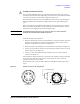
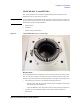
3. Place the B2220A so that the contact side (bottom side) faces up.
4. Unscrew and remove the contact protector from the bottom cover.
Keep the protector in trust. You may need it for move in future.
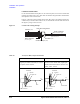
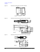
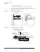
5. Attach your test fixture on the E3140A Test Fixture Adapter.
6. Mount the test fixture adapter on the B2220A.
7. Connect the connection cables. See “Model 300/400: To Connect Measurement
Cables” on page 2-19.