
Technical data


Agilent 41000 Administration Guide, Edition 3 2- 13
Installation and Operation
Installation
Model 100/200: To Make Your Connector Panel
This section is for you who do not use the Agilent 16495 connector plate.
If you want to mount connectors that accept the measurement cables from the instruments
directly on your own connector panel, test fixture, or shielding box, perform the following
procedure.
1. Select the appropriate parts for your application. See Table 2-7.
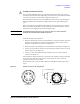
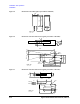
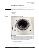
2. Make the holes and mount the connectors on your connector panel. See Table 2-8.
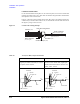
For Kelvin connections using the 4156C SMU, use Agilent 16493K Kelvin cable. A
Kelvin cable requires a Kelvin triaxial connector, which has two connector holes and
three screw holes.
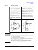
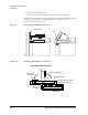
3. Build the interlock circuit shown in “To Make an Interlock Circuit” on page 2-11.
4. Attach cables from the connectors to the DUT (device under test). See Table 2-4, Table
2-5, and Table 2-6.
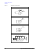
Table 2-7 Recommended Parts
Usage Agilent Part No. Description
Making an interlock
circuit
1252-1419C Interlock Connector (6 pin, female)
3101-0302 or 3101-3241 Switch
1450-0641 LED (V
F
≅ 2.1 V @ I
F
= 10 mA)
8150-5680 Wire
GNDU output connections 1250-2457 Triaxial Connector (female)
8121-1189 or 8150-2639 Coaxial Cable or Wire
SMU output connections 1250-2457 Triaxial Connector (female)
8121-1191 Low Noise Coaxial Cable
AUX output connections 1250-0118 BNC Connector (female)
8150-0447 Wire
8120-0102 or 8121-1191 Low Noise Coaxial Cable