
Technical data


Agilent 41000 Administration Guide, Edition 3 2- 11
Installation and Operation
Installation
To Make an Interlock Circuit
The Agilent E5270B/4155C/4156C provides an interlock terminal to prevent you from
receiving an electrical shock from high voltage (more than ±42 V). If the interlock terminal
is open, the instrument cannot force high voltage more than ±42 V.
You must install an interlock circuit on a shielding box and connect it to the instrument’s
Interlock terminal to prevent hazardous voltages when the door of the shielding box is
open.
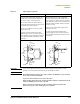
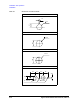
Figure 2-4 shows the pin assignments of the interlock connector mounted on a connector
plate or test fixture. The left side is the pin assignments seen from the plug side, and the
right side is the pin assignments seen from the soldering side.
WARNING Potentially hazardous voltages may be present at the Force, Guard, and Sense
terminals when the interlock terminals are shorted.
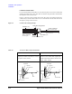
Install the interlock circuit as follows:
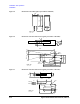
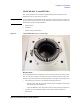
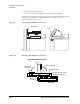
1. Mount two mechanical switches on your shielding box, so that the switches close when
the door of the shielding box is closed, and open when the door is opened. For the
dimensions of the switch, see
Figure 2-6 and Figure 2-7.
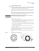
2. Mount an LED on your shielding box. For the dimensions of the LED, see Figure 2-5.
3. Use wire to connect the two switches in series between pin number 1 and 2 (or 3) of the
interlock connector. See
Figure 2-4.
4. Use wire to connect the LED between pin number 4 and 5 (or 6) of the interlock
connector. See
Figure 2-4.
If the instrument’s Interlock connector is connected to the interlock circuit, the instrument
cannot force more than ±42 V when the door is open. When the door is closed, the
instrument can force more than ±42 V.
When more than ±42 V is forced from an SMU, the LED lights to indicate high voltage
output.
Figure 2-4 Interlock Connector Pin Assignments
3OXJVLGH9LHZ
,QWHUORFN6ZLWFK
:LULQJ6LGH9LHZ
/('