
Technical data


Agilent 41000 Administration Guide, Edition 3 2- 9
Installation and Operation
Installation
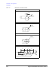
Table 2-5 SMU Output Connections
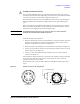
CAUTION Never connect the Guard terminal to any output, including circuit common, chassis
ground, or any other guard terminal. Doing so will damage the SMU.
WARNING Potentially hazardous voltages, up to ±100 V (±200 V for HPSMU), are present at the
Force, Sense, and Guard terminals.
To prevent electrical shock, do not expose these lines.
Before turning the instrument on, connect the Intlk terminal to a switch that turns off
when the shielding box access door is opened.
Before you touch any connections to these terminals, turn the instrument off,
disconnect the power cable, and discharge any capacitors.
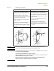
Kelvin connections non-Kelvin connections
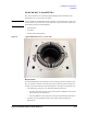
Use low-noise coaxial cable (Agilent part
number 8121-1191) from the connector to
the prober, socket, or DUT as shown.
To cancel the effects of cable resistance,
connect the Sense line and Force line as close
as possible to the DUT terminal.
To prevent oscillations, do not use cables
longer than 1.5 m.
To make accurate measurements when
applying high currents, extend the guard as
far as possible from the front panel connector
to the DUT. Physically stabilize the cables
with tape.
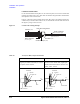
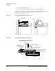
The following figure is when the Kelvin
triaxial cable is used. If the triaxial cable is
used, connect the cable to the Force terminal
only. With this connection, the measurement
data will include residual resistance from the
connection cable.
Use low-noise coaxial cable (Agilent part
number 8121-1191).
To make accurate measurements when
applying high currents, extend the guard as
far as possible from the front panel connector
to the DUT.
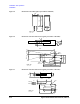
To
DUT
Insulator
FORCE
SENSE
Insulator
Coaxial Cable
Triaxial
Connector
Plate
GUARD
GUARD
To
DUT
Insulator
FORCE
SENSE
Insulator
Coaxial Cable
Triaxial
Connector
Plate
GUARD
GUARD