
Technical data


2- 6 Agilent 41000 Administration Guide, Edition 3
Installation and Operation
Installation
Model 100/200: To Connect 16495
The available connector plates are listed in Table 2-1. For connector plate installation
information, refer to Agilent 16495 Installation Guide.
For the connections between the instruments and the connector plate, use the measurement
cables listed in
Table 2-2 and Table 2-3, and connect them to the appropriate connectors.
For the connections over the connector plate, see the following tables.
• Table 2-4 shows the GNDU output connections over the connector plate.
• Table 2-5 shows the SMU output connections over the connector plate.
• Table 2-6 shows the AUX output connections over the connector plate.
Also make the interlock circuit and connect it to the instrument’s Interlock terminal. For
details, see
“To Make an Interlock Circuit” on page 2-11. The Agilent E5270B/4155C/
4156C provides the interlock function. If the interlock terminal is open, the instrument
cannot force high voltage more than ±42 V.
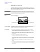
NOTE Making non-Kelvin connection
The Force terminals can be used to force and measure DC voltage or current. If you want to
simplify the cable connections, open the Sense terminals and connect the Force terminals
only to the connector plate by using the triaxial cables.
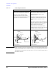
If you make the kelvin connection, use both Force and Sense terminals. Connecting the
Force and Sense lines together at the terminal of the device under test minimizes the
measurement error caused by the residual resistance of the connection cables. The kelvin
connection is effective for the low resistance measurement and the high current
measurement.
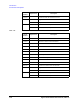
Table 2-1 Connector Plates
Model
Option Item
1
1. Option 001 provides the through connectors except for the Interlock connector that provides the solder-
ing patterns at the back side. For the option 002, the back of each connector is designed for soldering.
Connectors
16495F 16495F-001 Triax. (f-f) × 12, GNDU (f-f) × 1, Interlock (f) × 1
16495F-002 Triax. (f) × 12, GNDU (f) × 1, Interlock (f) × 1
16495G 16495G-001 Triax. (f-f) × 24, GNDU (f-f) × 1, Interlock (f) × 1
16495G-002 Triax. (f) × 24, GNDU (f) × 1, Interlock (f) × 1
16495H 16495H-001 Triax. (f-f) × 6, Coax. (f-f) × 6, GNDU (f-f) × 1, Interlock (f) × 1
16495H-002 Triax. (f) × 6, Coax. (f) × 6, GNDU (f) × 1, Interlock (f) × 1
16495J 16495J-001 Triax. (f-f) × 8, Coax. (f-f) × 4, GNDU (f-f) × 1, Interlock (f) × 1
16495J-002 Triax. (f) × 8, Coax. (f) × 4, GNDU (f) × 1, Interlock (f) × 1
16495K 16495K-001 Connector Plate with Rubber Holder