
Technical data

1- 12 Agilent 41000 Administration Guide, Edition 3
Introduction
System Cabinet
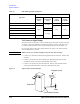
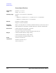
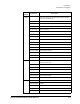
Table 1-6 PDU/EMO Operation and Response
To Connect a Signal Lamp
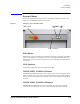
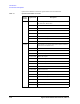
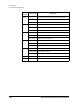
This section shows an example to connect a signal lamp or alarm that is used to notify that
AC power to the power distribution unit (PDU) is stopped. Connect a signal lamp to the
Ext. Alarm 2 (NO) terminals as shown in the following example. Also see
Figure 1-4.
Do not use the outlets in the system cabinet. Because AC power to the outlets will stop
when the EMO button is pressed.
WARNING While at work, never connect anything to the power line outlet for safety.
1. Connect a wire between a terminal of the signal lamp and one of the Ext. Alarm 2 (NO)
terminals.
2. Connect a wire between the other terminal of the signal lamp and the power plug
terminal that will be connected to the NEUTRAL of the outlet.
3. Connect a wire between the other side of the Ext. Alarm 2 (NO) terminals and the
power plug terminal that will be connected to the LINE of the outlet.
Figure 1-4 Signal Lamp Connection Example
Operation
Response
AC power to
controller
outlets
AC power to
instruments
outlets
Ext. Alarm
1 (NC)
terminals
Ext. Alarm
2 (NO)
terminals
Sets Main Switch to ON not supply
not supply
Open Close
Presses System Switch
supply Close Open
Presses ON Button on EMO Panel supply
Presses OFF Button on EMO Panel
not supply
Opens Remote Ctrl.
Presses EMO Button or opens Ext. EMO not supply Open Close
To Ext. alarm 2 terminal
Emergency lamp
Outlet
EMO switch