
Technical data


Agilent 41000 Administration Guide, Edition 3 6- 5
Probe Card Interface
Product Overview
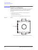
Interlock Circuit
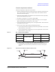
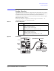
The Agilent B2220A provides the interlock circuit to support the interlock function of the
instrument such as the Agilent 4155/4156/E5270. The interlock circuit has been made by
connecting the high voltage indicator, prober sense switch, and interlock connector
internally. See
Figure 6-3. The connector type is same as the interlock connector of the
Agilent 4155/4156/E5270.
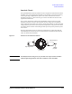
If you connect the interlock cable between the B2220A’s interlock connector and the
instrument’s interlock connector, the instrument can force voltage up to its maximum
output voltage when the prober sense switch is closed (make position), or limits the output
voltage when the prober sense switch is opened (break position). The prober sense switch
is normally opened. It will be closed during the male pin on the prober presses the prober
sense switch.
The high voltage indicator turns on during the instrument forces voltage more than the
value limited by the interlock function. For the instrument’s interlock function and limit
value, see manual of the instrument.
Figure 6-3 Interlock Circuit and Prober Male Pin
WARNING Potentially hazardous voltages may be presented at the output contact assemblies
when the high voltage indicator is lit. Do not touch the contact assemblies.
3UREHUVHQVHVZLWFK
+LJKYROWDJHLQGLFDWRU
,QWHUORFNFRQQHFWRU
RXWVLGHYLHZ
0DOHSLQ
RQSUREHU
WR
WR
WR
WR
WR
WR