
Technical data


6- 4 Agilent 41000 Administration Guide, Edition 3
Probe Card Interface
Product Overview
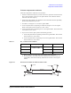
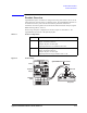
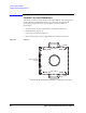
The interconnections of the probe card interface are quite simple. The inputs 1 through 48
are connected to the outputs 1 through 48 respectively. Then, the triaxial connector’s center
and middle conductors are connected to the pins A and B of the contact assembly as shown
in
Figure 6-2. And the outer conductor is connected to common. In addition, the middle
conductor is also connected to the shield plate of the contact assembly.
For the source monitor unit (SMU) connections, the force (or sense) terminal will be
connected to the center conductor and the signal appears on the pin A (cylinder hole side).
And the guard terminal will be connected to the middle conductor and the signal appears
on the pin B and the shield plate. The force and sense lines should be used to make a
Kelvin connection path.
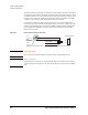
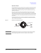
Figure 6-2 Input-Output Internal Connections
CAUTION SMU guard signal
Never connect the guard line/pattern to anything. Doing so will damage the unit.
NOTE Kelvin connections
To make a Kelvin connection, use two input/output paths. For example, connect a Kelvin
connection path to the input pair 11-12. Then the output pair 11-12 can work for a Kelvin
path.
&HQWHU
0LGGOH
2XWHU
%$LQSXWWULD[LDOFRQQHFWRU
%$RXWSXWFRQWDFWSLQV
3LQ$WR&HQWHU
3LQ%WR0LGGOH
6KLHOGSODWHWR0LGGOH
&\OLQGHUKROHVLGH
3LQ$
3LQ%