
Technical data


Agilent 41000 Administration Guide, Edition 3 5- 25
Measurement Techniques
Capacitance Measurements
To obtain compensation coefficients
Obtain the compensation coefficients as shown below.
1. Select the measurement frequency (Fmeas) used for the capacitance measurement of a
device under test (DUT), and set it to the Agilent 4284A. The coefficients must be
measured at the same frequency.
2. Perform the Agilent 4284A open calibration at the measurement terminal. Optionally,
perform short calibration if you want.
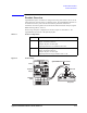
3. See Table 5-7 and Figure 5-13, and set the Agilent 4284A.
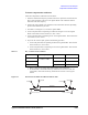
4. Connect the path/cable corresponding to C3H shown in Figure 5-12 to the Agilent
4284A. Then measure and record the R, L, and C values.
5. Connect the path/cable corresponding to C3L to the Agilent 4284A. Then measure and
record the R, L, and C values.
6. If you use the connector plate, perform the following procedure.
a. Connect the path/cable corresponding to C2H to the Agilent 4284A. Then measure
and record the R, L, and C values.
b. Connect the path/cable corresponding to C2L to the Agilent 4284A. Then measure
and record the R, L, and C values.
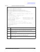
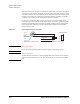
Table 5-7 R, L, C Measurement Conditions
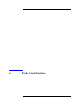
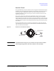
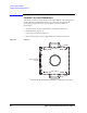
Figure 5-13 Measurement Terminals of C2H/C2L/C3H/C3L Path
Parameter Frequency Function Terminals
R
1 kHz to 1 MHz
1
1. Select 1 point. Do not change while measurements of all coefficients.
− A and B
L SERIES
see note
2
2. For triaxial cable, connect B to F directly, and measure L between A and E. For
coaxial cable, connect B to D directly, and measure L between A and C. Ignore
E and F.
C PARALLEL A and C
$
%
&
'
)RUFHRU6HQVH
)RUFHRU6HQVH
,QVXODWRU
7ULD[LDO&DEOH
(
*XDUG
)
*XDUG
*URXQG
*URXQG