
Technical data


5- 10 Agilent 41000 Administration Guide, Edition 3
Measurement Techniques
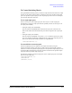
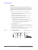
Kelvin Connections
To make force-sense connection at PC I/F input
To keep the Kelvin connection up to the Agilent B2220A probe card interface (PC I/F)
input, not output, see
Table 5-3 instead of Table 5-2.
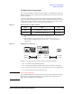
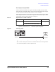
Connect the adapter to the PC I/F input, then connect the GNDU cable between the GNDU
and the adapter. The path over the PC I/F input will be the non-Kelvin connection.
Table 5-3 Required Cables for GNDU Connection (non-Kelvin over PC I/F input)
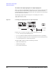
To pass GNDU output through SWM
If you have to pass the GNDU output through the Agilent B2200 switching matrix (SWM),
use the connection cables listed in
Table 5-4.
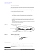
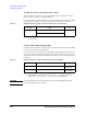
Connect the GNDU Kelvin cable between the GNDU and the SWM input. And connect the
Kelvin cable between the SWM output and the PC I/F input. The Kelvin connection can be
supported over the PC I/F output. To make the sense points, see
“Force-sense connections”
on page 5-6.
Table 5-4 Required Cables for GNDU Connection (through Agilent B2200)
CAUTION Do not apply high current over the allowable current of the Agilent B2200. The high
current may damage the switch module.
From Cable To
GNDU 16493L GNDU cable PC I/F Input
N1254A-107 Triax(m)-Triax(f) adapter
1
1. This adapter connects the center conductor (sense line) and the middle conduc-
tor (force line).
From Cable To
GNDU 16493N-001 GNDU Kelvin cable for B2200
SWM Input
1
1. Agilent B2200A/B2201A SWM input pairs 1-2, 3-4, 5-6, or 7-8.
SWM Output 16494C Kelvin triaxial cable
PC I/F Input
2
2. Agilent B2220A PC I/F input pairs 1-2, 3-4, 5-6, ... , or 47-48 for 48 pin con-
figuration, and 2-4, 6-8, 10-12, ... , or 46-48 for 24 pin configuration.