
Technical data


Agilent 41000 Administration Guide, Edition 3 5- 9
Measurement Techniques
Kelvin Connections
To Connect Ground Unit
To use the ground unit (GNDU) of the Agilent 41501B or E5270B, connect the GNDU
output to the probe card interface (PC I/F) input, not the switching matrix input. See
Figure
5-5. Table 5-2 lists the connection cables required to connect the GNDU.
Connect the adapter to the PC I/F input, then connect the GNDU cable between the GNDU
and the adapter. The Kelvin connection can be supported over the PC I/F output. To make
the sense points, see
“Force-sense connections” on page 5-6.
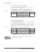
Table 5-2 Required Cables for GNDU Connection
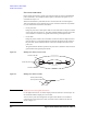
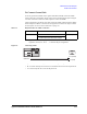
Figure 5-5 Connecting GNDU
In Figure 5-5, M, and A are integer, and have the following meaning.
• M: 1 to 24 for the 48 pin PC I/F or the even number from 2 to 24 for the 24 pin PC I/F.
• A: 1 for the 48 pin PC I/F or 2 for the 24 pin PC I/F.
From Cable To
GNDU 16493L GNDU cable
PC I/F Input
1
1. Agilent B2220A PC I/F input pairs 1-2, 3-4, 5-6, ... , or 47-48 for 48 pin con-
figuration, and 2-4, 6-8, 10-12, ... , or 46-48 for 24 pin configuration.
E5250-60044 Triax-Dual Triax adapter
/*1'8FDEOH.HOYLQDGDSWHU
*1'8)6
3&,)0$
3&,)0