
Technical data


5- 8 Agilent 41000 Administration Guide, Edition 3
Measurement Techniques
Kelvin Connections
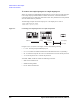
To connect non-couple input ports to couple output ports
When you control the Agilent B2200 switching matrix to connect the non-couple input port
to the couple output port that the Kelvin cable is connected to, control the switches to
connect the input port to both lines of the Kelvin cable. They should be the same potential
when the measurement is performed.
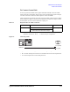
The following example connects the input port 1 to the output ports 11 and 12.
:ROUT:CONN:RULE ALL,FREE
:ROUT:CLOS (@00111,00112)
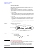
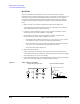
Figure 5-4 Connecting Non-couple Input Ports to Couple Output Ports
In Figure 5-4, L, N, M, and A are integer, and have the following meaning.
• L: 1 to 8. Used to specify the SWM input port.
•N: 1 to 6× (number of modules installed in the mainframe from slot 1 sequentially).
• M: 1 to 24 for the 48 pin PC I/F or the even number from 2 to 24 for the 24 pin PC I/F.
• A: 1 for the 48 pin PC I/F or 2 for the 24 pin PC I/F.
And SMU, SWM, and PC I/F indicate the following instrument.
• SMU: Source Monitor Unit
• SWM: Switching Matrix
• PC I/F: Probe Card Interface
608)RUFH
$WULD[LDOFDEOH
3&,)0$
&.HOYLQFDEOH
6:01
6:01
3&,)0
6:0/