
Technical data


5- 6 Agilent 41000 Administration Guide, Edition 3
Measurement Techniques
Kelvin Connections
Force-sense connections
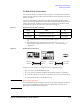
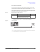
Kelvin output sense and force appear on the adjacent output pins of the Agilent B2220A
probe card interface. For example, if a Kelvin path is connected to the inputs 1-2, it is
extended to the output 1-2.
When the measurement is performed, the force and sense must be connected together.
There is the following ways to make the force-sense connections. Select the way suitable
for your measurement environment, and make it.
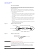
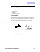
• On the probe card
Design the probe card so that a probe needle is connected to both two adjacent contacts
on the probe card. See
Figure 5-2. The guard terminals should be opened on the probe
card or should be connected to the guard terminal of the guarded probe needle.
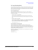
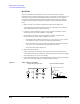
•On the wafer
Design the pattern so that a device terminal is connected to both two adjacent contact
pads. See
Figure 5-3. The pads should be contacted by the adjacent probe needles on
the probe card, and the needles should be connected to the adjacent contacts on the
probe card.
The guard terminals should be opened on the probe card or should be connected to the
guard terminal of the guarded probe needle.
Figure 5-2 Making Sense Points on Probe Card
Figure 5-3 Making Sense Points on Wafer
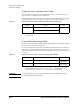
NOTE Differences from the Agilent 4070 series
For the Agilent 4070 series, one matrix output provides the both force and sense pins. So
the maximum 48 Kelvin output ports can be made.
You can use the probe cards designed for the Agilent 4070. However, for the Kelvin
connection, the sense points (force-sense connections) must be made on the wafer as
shown in Figure 5-3.
&RQWDFWIRU3LQ0$
&RQWDFWIRU3LQ0
&RQWDFWIRU*XDUG
&RQWDFWSDGIRU3LQ0$
&RQWDFWSDGIRU3LQ0
WRGHYLFH