
Technical data


Agilent 41000 Administration Guide, Edition 3 5- 5
Measurement Techniques
Kelvin Connections
To Make Kelvin Connections
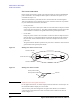
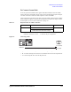
The instruments should be connected as shown in Figure 5-1 to make Kelvin connections.
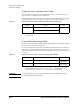
Table 5-1 lists the connection cables required to make the Kelvin connection of the source
monitor unit (SMU).
Connect the 16493K Kelvin cable between the SMU and the switching matrix (SWM)
input. And connect the 16494C Kelvin cable between the SWM output and the probe card
interface (PC I/F) input. The Kelvin connection can be supported over the PC I/F output.
To make the sense points, see
“Force-sense connections” on page 5-6.
Table 5-1 Required Cables for SMU Connection
Figure 5-1 Making Kelvin Connections
In Figure 5-1, K, N, M, and A are integer, and have the following meaning.
• K: 1 to 4. Used to specify the SWM input port.
•N: 1 to 6× (number of modules installed in the mainframe from slot 1 sequentially).
• M: 1 to 24 for the 48 pin PC I/F or the even number from 2 to 24 for the 24 pin PC I/F.
• A: 1 for the 48 pin PC I/F or 2 for the 24 pin PC I/F.
NOTE Kelvin input-output paths
The Agilent B2220A probe card interface (PC I/F) uses two input-output paths to make one
Kelvin connection. Maximum 12 Kelvin paths are available for the 24 pin PC I/F, 24
Kelvin paths are available for the 48 pin PC I/F.
From Cable To
SMU 16493K Kelvin triaxial cable
SWM Input
1
1. Agilent B2200A/B2201A switching matrix (SWM) input pairs 1-2, 3-4, 5-6, or
7-8.
SWM Output 16494C Kelvin triaxial cable
PC I/F Input
2
2. Agilent B2220A probe card interface (PC I/F) input pairs 1-2, 3-4, 5-6, ... , or
47-48 for 48 pin configuration, and 2-4, 6-8, 10-12, ... , or 46-48 for 24 pin
configuration.
608)RUFH
..HOYLQFDEOH
6086HQVH
3&,)0$
&.HOYLQFDEOH
6:01
6:01
3&,)0
6:0.
6:0.