
Technical data


Calibration 3
U2761A Service Guide 35
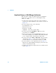
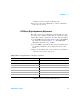
4 Fill in the table below using the measurement results in
Table 3- 13.
Table 3 - 14 Sine wave flatness worksheet
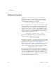
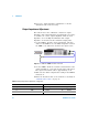
5 Use the DMM to perform the AC voltage measurement at
the output terminal for each setup shown in the table
below.
6 Enter the measured value to the U2761A as described in
“Calibration Procedure” on page 30.
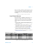
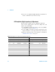
Parameter Calculation Offset
Offset
–20dB
dB
Offset
0dB
dB
Offset
+20dB
dB
Offset 20
V
value 16()
V
value 15()
------------------------log×=
Offset 20
V
value 19()
V
value 18()
------------------------log×=
Offset 20
V
value 22()
V
value 20()
------------------------log×=
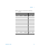
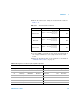
Table 3-15 Configuration for 50% ramp AC amplitude adjustment
U2761A DMM
Setup Function Frequency Amplitude Lower margin Measurement Upper margin
23 50% Ramp 1.00000 kHz 28 mVrms 26.6 mVrms Vrms 29.4 mVrms
24 50% Ramp 1.00000 kHz 50 mVrms 47.5 mVrms Vrms 52.5 mVrms
25 50% Ramp 1.00000 kHz 70 mVrms 65.1 mVrms Vrms 74.9 mVrms
26 50% Ramp 1.00000 kHz 500 mVrms 465 mVrms Vrms 535 mVrms
27 50% Ramp 1.00000 kHz 700 mVrms 651 mVrms Vrms 749 mVrms
28 50% Ramp 1.00000 kHz 2.500 Vrms 2.325 Vrms Vrms 2.675 Vrms