
Technical data


3 Calibration
34 U2761A Service Guide
4 Proceed to AC amplitude (High Impedance) adjustment or
exit the calibration mode when necessary.
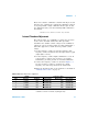
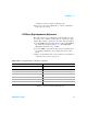
AC Amplitude (High Impedance) Adjustment
This procedure calculates the AC amplitude calibration
factor of three output paths for Sine wave, Ramp wave, and
Square wave individually.
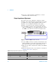
1 Set the DMM to measure AC voltage. Connect the DMM to
the U2761A as shown in Figure 3- 3.
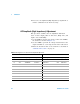
2 Use the DMM to perform AC voltage measurement at the
output terminal for each setup shown in the table below.
3 Enter the measured value to the U2761A as described in
“Calibration Procedure” on page 30.
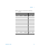
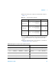
Table 3-13 Configuration for Sine wave AC amplitude adjustment
U2761A DMM
Setup Function Frequency Amplitude Lower margin Measurement Upper margin
14 Sine 1.00000 kHz 32 mVrms 30.4 mVrms Vrms 33.6 mVrms
15 Sine 1.00000 kHz 60 mVrms 57.0 mVrms Vrms 63.0 mVrms
16 Sine 100.000 kHz 60 mVms 57.0 mVrms Vrms 63.0 mVrms
17 Sine 1.00000 kHz 80 mVrms 74.4 mVrms Vrms 85.6 mVrms
18 Sine 1.00000 kHz 600 mVrms 558 mVrms Vrms 642 mVrms
19 Sine 100.000 kHz 600 mVrms 558 mVrms Vrms 642 mVrms
20 Sine 1.00000 kHz 800 mVrms 744 mVrms Vrms 856 mVrms
21 Sine 1.00000 kHz 3.000 Vrms 2.79 Vrms Vrms 3.21 Vrms
22 Sine 100.000 kHz 800 mVrms 744 mVrms Vrms 856 mVrms