
Technical data


Calibration 3
U2761A Service Guide 31
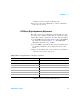
Please note that the calibration constant will only be stored
after the user completes the subsequent calibration setup in
each group within a single calibration mode login. To exit
the calibration mode, send the following SCPI command to
the U2761A.
CALibration:SECure:STATe ON,U2761A
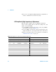
Internal Timebase Adjustment
The U2761A relies on a VCTCXO to generate the precision
clock to drive the DDS architecture. This procedure
determines the suitable control voltage for the VCTCXO to
output the correct frequency. This procedure implements a
three-time approach to obtain the best possible control
voltage.
1 Set the frequency counter to measure frequency. The
frequency counter resolution must be higher than 0.1 ppm
(eight digits or more).
2 Set the frequency counter input termination to 50
Ω. If
your frequency counter does not have a 50
Ω input
termination, you must provide an external termination.
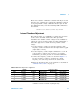
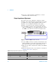
3 Connect the frequency counter as shown in Figure 3- 1.
Use the frequency counter to measure the output
frequency for each setup shown in the table below.
4 Enter the measured value to the U2761A as described in
“Calibration Procedure” on page 30.
1 Calibration constant is stored after completing this setup.
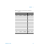
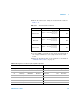
Table 3-10 Timebase adjustment configuration
U2761A Frequency counter
Setup Frequency Amplitude Lower margin Measurement Upper margin
1 < 10 MHz 1 Vpp 9.999000 MHz MHz 9.999800 MHz
2 > 10 MHz 1 Vpp 10.000200 MHz MHz 10.001000 MHz
3 _ 10 MHz 1 Vpp 9.999900 MHz MHz 10.000100 MHz
4
1
= 10 MHz 1 Vpp 9.999990 MHz MHz 10.000010 MHz