
Technical data


3 Calibration
20 U2761A Service Guide
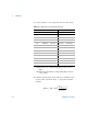
2 Use the DMM to make the resistance measurement at the
output terminal for each setup shown in the table below.
The expected measured value is approximately 50 Ω..
3 This procedure will require you to unsecure the
instrument for calibration. See “Calibration Procedure” on
page 30 for more information on how to unsecure the
instrument for calibration. The calibration constant is not
stored to the U2761A after completing the setup.
4 Exit the Calibration Mode.
DC Offset (High Impedance) Verification
This procedure verifies the accuracy of the DC offset with
high impedance load (DMM input impedance of 10 M
Ω).
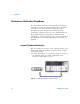
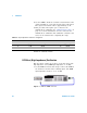
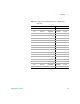
1 Set the DMM to measure DC voltage. Connect the DMM to
the U2761A as shown in the following figure. The DMM
input impedance must be set to 10 M
Ω.
Figure 3-3 U2761A to DMM connection
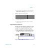
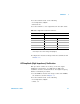
Table 3 - 3 Output impedance verification configuration
U2761A DMM
CalSet Output path Lower margin Measurement Upper margin
5
–20 dB 49.5 ΩΩ50.5 Ω
60 dB 49.5 ΩΩ50.5 Ω
7 +20 dB 49.5 ΩΩ50.5 Ω