Agilent U2761A USB Modular Function/Arbitrary Waveform Generator Service Guide Agilent Technologies
Notices © Agilent Technologies, Inc., 2008–2013 Warranty No part of this manual may be reproduced in any form or by any means (including electronic storage and retrieval or translation into a foreign language) without prior agreement and written consent from Agilent Technologies, Inc. as governed by United States and international copyright laws. The material contained in this document is provided “as is,” and is subject to being changed, without notice, in future editions.
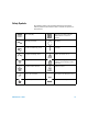
Safety Symbols The following symbols on the instrument and in the documentation indicate precautions which must be taken to maintain safe operation of the instrument.
General Safety Information The following general safety precautions must be observed during all phases of operation of this instrument. Failure to comply with these precautions or with specific warnings elsewhere in this manual violates safety standards of design, manufacture and intended use of the instrument. Agilent Technologies Inc. assumes no liability for the customer’s failure to comply with these requirements.
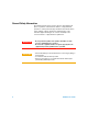
Environment Conditions This instrument is designed for indoor use and in the area with low condensation. The table below shows the general environmental requirements for this instrument. CAUTION Requirements Operating temperature 0 °C to 50 °C Operating humidity 20 to 85% RH noncondensing Storage temperature –20 °C to 70 °C Storage humidity 5 to 90% RH noncondensing The U2761A USB modular function/arbitrary waveform generator complies with the following safety and EMC requirements.
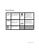
Regulatory Markings The CE mark is a registered trademark of the European Community.This CE mark shows that the product complies with all the relevant European Legal Directives. The C-tick mark is a registered trademark of the Spectrum Management Agency of Australia. This signifies compliance with the Australia EMC Framework regulations under the terms of the Radio Communication Act of 1992. ICES/NMB-001 indicates that this ISM device complies with Canadian ICES-001.
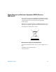
Waste Electrical and Electronic Equipment (WEEE) Directive 2002/96/EC This instrument complies with the WEEE Directive (2002/96/EC) marking requirement. This affixed product label indicates that you must not discard this electrical/electronic product in domestic household waste. Product Category: With reference to the equipment types in the WEEE directive Annex 1, this instrument is classified as a “Monitoring and Control Instrument” product.
In This Guide… 1 Characteristics and Specifications The characteristics and specifications of the U2761A are listed in this chapter. 2 Getting Started In this chapter, you will learn about the the self-test procedure for the U2761A. The information for returning the U2761A for calibration or servicing is also provided. 3 Calibration This chapter describes the performance verification and calibration procedures for the U2761A.
Declaration of Conformity (DoC) The Declaration of Conformity (DoC) for this instrument is available on the Web site. You can search the DoC by its product model or description. http://regulations.corporate.agilent.com/DoC/search.htm NOTE U2761A Service Guide If you are unable to search for the respective DoC, please contact your local Agilent representative.
THIS PAGE HAS BEEN INTENTIONALLY LEFT BLANK.
Contents 1 Characteristics and Specifications 1 Product Characteristics 2 Product Specifications and Characteristics 4 2 Getting Started 9 Introduction 10 Self-Test 10 Agilent Technologies Calibration Services 12 Calibration Interval 12 Types of Service Available 12 Extended Service Contracts 12 Obtaining Repair Service (Worldwide) 13 Repackaging for Shipment 14 Cleaning 14 3 Calibration 15 Introduction 16 Recommended Test Equipment 16 Test Consideration 17 Performance Verification Procedures 18 Intern
Calibration Procedure 30 Internal Timebase Adjustment 31 Output Impedance Adjustment 32 DC Offset (High Impedance) Adjustment 33 AC Amplitude (High Impedance) Adjustment 34 Amplitude Flatness (–20 dB Range) Adjustment 37 Amplitude Flatness (0 dB Range) Adjustment 39 Amplitude Flatness (+20 dB Range) Adjustment 41 4 Disassembly 43 General Disassembly 44 Disassembly Instructions 44 Reassembly Instructions 46 Replacement Parts 46 5 Troubleshooting 49 Troubleshooting 50 Index 51 xii U2761A Service Guide
List of Figures Figure 3-1 Figure 3-3 Figure 3-4 Figure 3-5 U2761A Service Guide U2761A to frequency counter connection 18 U2761A to DMM connection 20 U2761A to power meter connection 23 U2761A to DMM four-wire connection 32 xiii
List of Tables Table 3-1 Table 3-2 Table 3-4 Table 3-5 Table 3-6 Table 3-7 Table 3-8 Table 3-9 Table 3-10 Table 3-11 Table 3-12 Table 3-13 Table 3-14 Table 3-15 Table 3-16 Table 3-17 Table 3-18 Table 3-19 xiv Recommended test equipment 16 Configuration for timebase verification 19 Configuration for DC offset verification 21 Configuration for AC amplitude verification 22 AC amplitude verification worksheet 23 Configuration for AC amplitude flatness (–20 dB range) verification 25 Configuration for AC amplit
Agilent U2761A USB Modular Function/Arbitrary Waveform Generator Service Guide 1 Characteristics and Specifications Product Characteristics 2 Product Specifications and Characteristics 4 This chapter specifies the characteristics, environmental conditions, and specifications of the U2761A.
1 Characteristics and Specifications Product Characteristics REMOTE INTERFACE • Hi-Speed USB 2.0 • USBTMC 488.2 Class device [1] POWER CONSUMPTION • +12 VDC, 1.
Characteristics and Specifications 1 [1] Requires a direct USB connection to the PC so the appropriate driver can be installed in the USB modular instrument or USB DAQ module.
1 Characteristics and Specifications Product Specifications and Characteristics WAVEFORMS Standard Sine, Square, Ramp, Triangle, Pulse, DC Built-in arbitrary Exponential Rise, Exponential Fall, Negative Ramp WAVEFORM CHARACTERISTICS Sine Frequency range 1 μHz to 20 MHz (1 μHz resolution) Amplitude flatness 1 ≤ 100 kHz (relative to 1 kHz) 100 kHz to 1 MHz 0.35 dB 1 MHz to 20 MHz 0.
Characteristics and Specifications 1 Ramp, Triangle Frequency range 1 μHz to 200 kHz (1 μHz resolution) Linearity < 0.2% of peak output Programmable symmetry 0% to 100% Pulse Frequency range 500 μHz to 5 MHz (1 μHz resolution) Pulse width (period ≤ 10 s) 40 ns minimum, 10 ns resolution Overshoot < 3% Jitter (RMS) 300 ps + 0.
1 Characteristics and Specifications COMMON CHARACTERISTICS Amplitude Range 40 mVpp to 5 Vpp (Into 50 Ω load) 80 mVpp to 10 Vpp (Into open circuit) Accuracy 1 (across 50 Ω load at 1 kHz) ±1% of setting ±5 mV (±10 mV @ Hi-Z) Units Vpp, Vrms, dBm Resolution 4 digits DC offset Range (peak AC + DC) ±2.
Characteristics and Specifications 1 MODULATION AM Carrier waveforms Sine, Square, Ramp, Arbitrary Source Internal Internal modulation Sine, Square, Ramp, Arbitrary (2 mHz to 20 kHz) Depth 0.0% to 100.
1 Characteristics and Specifications SWEEP CHARACTERISTICS Waveforms Sine, Square, Ramp, Arbitrary Type Linear or Logarithmic Direction Up or Down Sweep time 1 ms to 500 s Trigger Single, External, or Internal TRIGGER CHARACTERISTICS Trigger input Input level TTL compatible Slope Rising or Falling, Selectable Pulse width > 100 ns Input impedance > 10 kΩ, DC coupled Latency < 500 ns Jitter (RMS) 6 ns (3.
Agilent U2761A USB Modular Function/Arbitrary Waveform Generator Service Guide 2 Getting Started Introduction 10 Self-Test 10 Agilent Technologies Calibration Services 12 Calibration Interval 12 Types of Service Available 12 Extended Service Contracts 12 Obtaining Repair Service (Worldwide) 13 Repackaging for Shipment 14 Cleaning 14 This chapter provides the self-test procedure for the U2761A USB modular function generator.
2 Calibration Introduction Self-Test A brief power-on self-test occurs automatically whenever the U2761A is turned on. This limited test assures that the instrument is capable of operation. To perform a complete self-test, send the following SCPI command to the U2761A. *TST? The U2761A will automatically perform the complete self-test procedure when the SCPI command is sent. The self-test will be completed in a few seconds. • If the self-test is successful, a zero (0) is returned.
Calibration 2 2 Click Start on the Self-Test form. 3 Click OK to continue when the message box appears. 4 Wait for a few minutes for the self-test to complete. 5 The result is displayed on the form once the self-test has completed.
2 Calibration Agilent Technologies Calibration Services When your U2761A is due for calibration, contact your local Agilent Service Center for a low-cost recalibration. The U2761A is supported on automated calibration systems, which allows Agilent to provide this service at a competitive price. Calibration Interval The U2761A should be verified and calibrated on a regular interval based on the measurement accuracy requirements of your application. A one-year interval is adequate for most applications.
Calibration 2 Obtaining Repair Service (Worldwide) To obtain service for your U2761A (in-warranty, under service contract, or post-warranty), contact your nearest Agilent Service Center. They will arrange to have your unit repaired or replaced, and are able to provide warranty or repair cost information where applicable. To obtain warranty, service, or technical support information you can contact Agilent at one of the following telephone numbers.
2 Calibration Repackaging for Shipment If the U2761A is to be shipped to Agilent for service or repair, make sure that you do the following. • Attach a tag to the U2761A identifying the owner and indicating the required service or repair. Include the model number and full serial number. • Place the U2761A in its original container with appropriate packaging material for shipping. • Secure the container with strong tape or metal bands.
Agilent U2761A USB Modular Function/Arbitrary Waveform Generator Service Guide 3 Calibration Introduction 16 Recommended Test Equipment 16 Test Consideration 17 Performance Verification Procedures 18 Internal Timebase Verification 18 Output Impedance Verification 19 DC Offset (High Impedance) Verification 20 AC Amplitude (High Impedance) Verification 21 Amplitude Flatness (–20 dB Range) Verification 23 Amplitude Flatness (0 dB Range) Verification 26 Amplitude Flatness (+20 dB Range) Verification 28 Calibra
3 Calibration Introduction If the U2761A fails any of the tests or if any abnormal test results are obtained, return the unit to the Agilent Service Center for readjustment. Recommended Test Equipment The recommended test equipment for the verification and calibration procedures are listed in the table below. Table 3-1 Recommended test equipment Instrument Digital multimeter (DMM) Minimum requirement AC volts • True rms • AC coupled • Accuracy: ±0.
Calibration 3 Test Consideration For optimum performance, all procedures should comply with the following recommendations. • Ensure that the calibration ambient temperature is stable and between 23 °C ± 3 °C. • The ambient relative humidity must be less than 80%. • Allow a one-hour warm-up period before verification or adjustment. • Keep the measurement cables as short as possible and consistent with the impedance requirement. • Use RG-58 or equivalent 50 Ω cable.
3 Calibration Performance Verification Procedures It is recommended to carry out performance verification tests when you first receive the U2761A. The performance verification test results should be compared to the specifications of the U2761A. You should repeat the performance verification tests at every calibration interval. If the U2761A fails the performance verification tests, adjustment or repair is required.
Calibration 3 2 Set the U2761A to the output shown in the table below and measure the output frequency. Make sure that the U2761A output is enabled. Table 3-2 Configuration for timebase verification U2761A Measurement Function Amplitude Frequency Nominal Error1 Sine 1.00 Vpp 10.0000 MHz 10.0000 MHz ±80 Hz 1 Based upon ±8 ppm for one year. 3 Compare the measured frequency with the test limit shown in Table 3- 2.
3 Calibration 2 Use the DMM to make the resistance measurement at the output terminal for each setup shown in the table below. The expected measured value is approximately 50 Ω.. 3 This procedure will require you to unsecure the instrument for calibration. See “Calibration Procedure” on page 30 for more information on how to unsecure the instrument for calibration. The calibration constant is not stored to the U2761A after completing the setup.
Calibration 3 2 Set the U2761A based on the following. • Load impedance: High-Z • Function: DC 3 Set the U2761A to each output listed in the table below. Table 3-4 Configuration for DC offset verification U2761A Measurement DC offset Nominal Error1 –5.000 VDC –5.000 VDC ±0.11 VDC –2.500 VDC –2.500 VDC ±0.06 VDC 0.000 VDC 0.000 VDC ±0.01 VDC +2.500 VDC +2.500 VDC ±0.06 VDC +5.000 VDC +5.000 VDC ±0.11 VDC 1 Based upon ±2% of offset setting ±10 mV (High-Z).
3 Calibration 3 Set the U2761A to each output listed in the table below. Table 3-5 Configuration for AC amplitude verification U2761A Measurement Function Frequency Amplitude Nominal Error1 Sine 1.00000 kHz 70 mVrms 70 mVrms ±4.236 mVrms Sine 100.000 kHz 70 mVrms 70 mVrms ±5.146 mVrms Sine 1.00000 kHz 700 mVrms 700 mVrms ±10.54 mVrms Sine 100.000 kHz 700 mVrms 700 mVrms ±19.64 mVrms Sine 1.00000 kHz 3.500 Vrms 3.500 Vrms ±38.54 mVrms Sine 100.000 kHz 3.500 Vrms 3.
Calibration 3 Table 3-6 AC amplitude verification worksheet U2761A DMM Calculation Measurement Offset Function Frequency Amplitude Sine 1.00000 kHz 70 mVrms Vrms Sine 100.000 kHz 70 mVrms Vrms Sine 1.00000 kHz 700 mVrms Vrms Sine 100.000 kHz 700 mVrms Vrms Sine 1.00000 kHz 3.500 Vrms Vrms Sine 100.000 kHz 3.
3 Calibration 2 Set the U2761A based on the following. • Load impedance: 50 Ω • Function: Sine wave • Frequency: 100 kHz • Amplitude: 35 mVrms (–16.108 dBm) 3 Set the power meter Filter Mode to Manual and set Average Length to 500 to improve measurement stability. Allow a minimum of 30 s between the time of setting the U2761A and collecting the measurement reading. 4 On the power meter, use the Relative Power function to set the current reading as the reference value.
Calibration 3 Table 3-7 Configuration for AC amplitude flatness (–20 dB range) verification U2761A U2761A Service Guide Measurement Function Amplitude Frequency Nominal Error Sine 35 mVrms 100.000 kHz 0.000 dB ±0.2 dB Sine 35 mVrms 160.000 kHz 0.000 dB ±0.35 dB Sine 35 mVrms 250.000 kHz 0.000 dB ±0.35 dB Sine 35 mVrms 400.000 kHz 0.000 dB ±0.35 dB Sine 35 mVrms 630.000 kHz 0.000 dB ±0.35 dB Sine 35 mVrms 1.00000 MHz 0.000 dB ±0.35 dB Sine 35 mVrms 1.60000 MHz 0.
3 Calibration Amplitude Flatness (0 dB Range) Verification This procedure verifies the high frequency AC amplitude flatness above 100 kHz on the 0 dB range relative to 1 kHz. 1 Connect the power meter to measure the output amplitude of the U2761A as shown in Figure 3- 4. 2 Set the U2761A based on the following. • Load impedance: 50 Ω • Function: Sine wave • Frequency: 100 kHz • Amplitude: 350 mVrms (+3.892 dBm) 3 Set the power meter Filter Mode to Auto if you have previously set it to Manual.
Calibration 3 Table 3-8 Configuration for AC amplitude flatness (0 dB range) verification U2761A U2761A Service Guide Measurement Function Amplitude Frequency Nominal Error Sine 350 mVrms 100.000 kHz 0.000 dB ±0.2 dB Sine 350 mVrms 160.000 kHz 0.000 dB ±0.35 dB Sine 350 mVrms 250.000 kHz 0.000 dB ±0.35 dB Sine 350 mVrms 400.000 kHz 0.000 dB ±0.35 dB Sine 350 mVrms 630.000 kHz 0.000 dB ±0.35 dB Sine 350 mVrms 1.00000 MHz 0.000 dB ±0.35 dB Sine 350 mVrms 1.
3 Calibration Amplitude Flatness (+20 dB Range) Verification This procedure verifies the high frequency AC amplitude flatness above 100 kHz on the +20 dB amplifier range relative to 1 kHz. 1 Connect the power meter and power sensor together to measure the output amplitude of the U2761A as shown in Figure 3- 4. 2 Set the U2761A based on the following. • Load impedance: 50 Ω • Function: Sine wave • Frequency: 100 kHz • Amplitude: 1.750 Vrms (+17.
Calibration 3 Table 3-9 Configuration for AC amplitude flatness (+20 dB range) verification U2761A U2761A Service Guide Measurement Function Amplitude Frequency Nominal Error Sine 1.750 Vrms 100.000 kHz 0.000 dB ±0.2 dB Sine 1.750 Vrms 160.000 kHz 0.000 dB ±0.35 dB Sine 1.750 Vrms 250.000 kHz 0.000 dB ±0.35 dB Sine 1.750 Vrms 400.000 kHz 0.000 dB ±0.35 dB Sine 1.750 Vrms 630.000 kHz 0.000 dB ±0.35 dB Sine 1.750 Vrms 1.00000 MHz 0.000 dB ±0.35 dB Sine 1.750 Vrms 1.
3 Calibration Calibration Procedure Calibration is necessary when the one-year calibration interval has expired, or whenever the U2761A fails any verification test. To enter the calibration mode, send the following SCPI command to the U2761A. CALibration:SECure:STATe OFF,U2761A Once the calibration state is unsecured, the U2761A is now in the calibration mode and setup is 0 by default. All the calibration setup is predetermined and transparent to the user.
Calibration 3 Please note that the calibration constant will only be stored after the user completes the subsequent calibration setup in each group within a single calibration mode login. To exit the calibration mode, send the following SCPI command to the U2761A. CALibration:SECure:STATe ON,U2761A Internal Timebase Adjustment The U2761A relies on a VCTCXO to generate the precision clock to drive the DDS architecture.
3 Calibration 5 Proceed to output impedance adjustment or exit the calibration mode when necessary. Output Impedance Adjustment The U2761A stores the calibration constant for output impedance. The output impedance measurement is necessary to calculate the correct output amplitude when the load impedance is not at High-Z termination. The output impedance is measured at three different output paths. 1 Set the DMM to measure offset-compensated, four-wire ohms. Set the DMM to use 100 NPLC integration.
Calibration 3 1 Calibration constant is stored after completing this setup. 5 Proceed to DC offset adjustment or exit the calibration mode when necessary. DC Offset (High Impedance) Adjustment The U2761A stores the calibration constant related to gain and offset of the internal system DAC to control the offset setting. This setting is used for both offset and DC outputs. 1 Set the DMM to measure DC voltage. Connect the DMM to the U2761A as shown in Figure 3- 3.
3 Calibration 4 Proceed to AC amplitude (High Impedance) adjustment or exit the calibration mode when necessary. AC Amplitude (High Impedance) Adjustment This procedure calculates the AC amplitude calibration factor of three output paths for Sine wave, Ramp wave, and Square wave individually. 1 Set the DMM to measure AC voltage. Connect the DMM to the U2761A as shown in Figure 3- 3. 2 Use the DMM to perform AC voltage measurement at the output terminal for each setup shown in the table below.
Calibration 3 4 Fill in the table below using the measurement results in Table 3- 13.
3 Calibration 7 Use the DMM to perform the AC voltage measurement at the output terminal for each setup shown in the table below. 8 Enter the measured value to the U2761A as described in “Calibration Procedure” on page 30. Table 3-16 Configuration for 50% pulse AC amplitude adjustment U2761A DMM Setup Function Period Amplitude Lower margin Measurement Upper margin 29 50% Pulse 1.00000 ms 44 mVrms 41.8 mVrms Vrms 46.2 mVrms 30 50% Pulse 1.00000 ms 90 mVrms 85.5 mVrms Vrms 94.
Calibration 3 Amplitude Flatness (–20 dB Range) Adjustment This procedure calibrates the AC amplitude flatness for high frequency using –20 dB attenuator. This calibration is performed using Sine wave at nominal amplitude of 30 mVrms across 50 Ω load. 1 Connect the power meter to measure the output amplitude of the U2761A as shown in Figure 3- 4. 2 Set the power meter Filter Mode to Manual and Averaging Length to 500, to improve the measurement stability.
3 Calibration Table 3-17 Configuration for AC amplitude flatness (–20 dB range) adjustment U2761A Power meter Setup Function Frequency Lower margin Measurement 35 Sine 100.000 kHz –0.2 dB (Offset–20dB) Upper margin +0.2 dB dB 36 Sine 780.000 kHz 37 Sine 1.56000 MHz 38 Sine 2.34000 MHz 39 Sine 3.13000 MHz 40 Sine 3.91000 MHz 41 Sine 4.69000 MHz 42 Sine 5.47000 MHz 43 Sine 6.25000 MHz 44 Sine 7.03000 MHz 45 Sine 7.81000 MHz 46 Sine 8.59000 MHz 47 Sine 9.
Calibration 3 Amplitude Flatness (0 dB Range) Adjustment This procedure calibrates the AC amplitude flatness for high frequency using 0 dB direct path. This calibration is performed using Sine wave at nominal amplitude of 300 mVrms across 50 Ω load. 1 Connect the power meter to measure the output amplitude of the U2761A as shown in Figure 3- 4. 2 Set the power meter Filter Mode to Auto if you have previously set it to Manual.
3 Calibration Table 3-18 Configuration for AC amplitude flatness ( 0 dB range) adjustment U2761A Power meter Setup Function Frequency Lower margin Measurement 62 Sine 100.000 kHz –0.2 dB (Offset0dB) Upper margin +0.2 dB dB 63 Sine 780.000 kHz 64 Sine 1.56000 MHz 65 Sine 2.34000 MHz 66 Sine 3.13000 MHz 67 Sine 3.91000 MHz 68 Sine 4.69000 MHz 69 Sine 5.47000 MHz 70 Sine 6.25000 MHz 71 Sine 7.03000 MHz 72 Sine 7.81000 MHz 73 Sine 8.59000 MHz 74 Sine 9.
Calibration 3 Amplitude Flatness (+20 dB Range) Adjustment This procedure calibrates the AC amplitude flatness for high frequency using +20 dB amplifier. This calibration is performed using Sine wave at nominal amplitude of 400 mVrms across 50 Ω load. 1 Connect the power meter to measure the output amplitude of the U2761A as shown in Figure 3- 4. 2 Set the power meter Filter Mode to Auto if you have previously set it to Manual.
3 Calibration Table 3-19 Configuration for AC amplitude flatness (+20 dB range) adjustment U2761A Power meter Setup Function Frequency Lower margin Measurement 89 Sine 100.000 kHz –0.2 dB (Offset+20dB) Upper margin +0.2 dB dB 90 Sine 780.000 kHz 91 Sine 1.56000 MHz 92 Sine 2.34000 MHz 93 Sine 3.13000 MHz 94 Sine 3.91000 MHz 95 Sine 4.69000 MHz 96 Sine 5.47000 MHz 97 Sine 6.25000 MHz 98 Sine 7.03000 MHz 99 Sine 7.81000 MHz 100 Sine 8.59000 MHz 101 Sine 9.
Agilent U2761A USB Modular Function/Arbitrary Waveform Generator Service Guide 4 Disassembly General Disassembly 44 Disassembly Instructions 44 Reassembly Instructions 46 Replacement Parts 46 This chapter describes the procedure to disassemble the U2761A. The information on the replacement parts is also provided.
4 Disassembly General Disassembly This chapter provides the step-by-step guide to dismantle the module. To reassemble the module, follow the instructions in reverse order. The removable assemblies include the following.
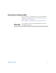
Disassembly Front metal piece 4 Remove the two indicated screws from the front metal piece. Screws Gently pull the front metal piece out, which is attached to the carrier and measurement boards.
4 Disassembly Reassembly Instructions The reassembly process is simply the reverse of disassembly. Replacement Parts This section provides the information of orderable replacement parts for the U2761A. You can order the replacement parts through Agilent website or you can contact the nearest Agilent Sales Office or Service Centre. To search for the replacement part number online, follow the steps below. 1 Launch your Internet Explorer to access Agilent website (www.agilent.com).
Disassembly 4 3 You can search for the replacement parts by entering a specific replacement part number or by instruments. • To search by part number, type the replacement part number in the text box as shown below. • To search by instrument, type the model number in the text box and click View Parts to select a particular replacement part. 4 The result of your search will appear and click View Parts for the selected instrument.
4 Disassembly THIS PAGE HAS BEEN INTENTIONALLY LEFT BLANK.
Agilent U2761A USB Modular Function/Arbitrary Waveform Generator Service Guide 5 Troubleshooting Troubleshooting 50 This chapter provides the general information to troubleshoot the U2761A.
5 Troubleshooting Troubleshooting This section offers suggestions for solving general problems that you may encounter with the U2761A. It guides you on what to check in the following situations. • Power indicator LED is not lit. Verify that the AC power cord is connected to the power inlet of the U2761A. • Power indicator LED is lit but the USB indicator LED is not lit. Verify that the USB cable is properly connected to the PC and USB inlet of the U2761A.
Index A accuracy, 5, 12, 16, 18, 19, 20 adjustment +20 dB range flatness, 40 0 dB range flatness, 38 -20 db range AC flatness, 36 AC amplitude, 33 DC offset, 32 output impedance, 31 timebase, 30 Agilent calibration services, 12 measurement manager, 10 recommended models, 16 AM carrier waveform, 6 depth, 6 ambient relative humidity, 17 temperature, 17 arbitrary, 3, 4 ASK carrier waveform, 6 Asymmetry, 3 characteristics common, 5 product, 2 specifications/measurement, 3 sweep, 7 trigger, 7 waveform, 3 compli
Index P symmetry, 4 phase noise, 3 PM 6 carrier waveform, 6 phase deviation, 6 power consumption, 2 power meter, 16, 22, 23, 25, 27, 36, 38, 40 power sensor, 16 product dimensions, 2 specifications, 3 Programmable symmetry, 4 protection, 5 PSK carrier waveform, 6 deviation, 6 pulse, 4, 7, 35 T R Ramp, 4 reassembly, 46 recommended test equipment, 16 remote interface, 2 repackaging, 14 repair service, 13 resolution, 5 rise/fall time, 3, 4 RMS, 3, 4, 7 test consideration, 17 trigger input, 7 output, 7 tr
www.agilent.