
User's Manual


Performing Tests
TX Power Adjustment
Chapter 4
71
Performing Tests
TX Power Adjustment
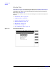
This adjustment procedure provides an analog display of power measurements. This
mode is useful when making adjustments to power levels on a transmitter.
Features of the power meter display include:
• Tick marks on the meter to indicate when a power level setting is within limits.
• Audible tones to indicate whether the power reading falls within limits.
• A USER key to choose between measurement units of dBm or Watts.
This test may be performed with the Base Station in service using the Base Station TX
Test Port, or out-of-service using the Base Station TX Antenna Port (see “Which Base
Station Port to Use – TX Test or TX Antenna?” on page 35 and “Base Station
Configuration” on page 39.
Parameters and Specifications Used
The following parameters and specifications are used when running this test. See
Chapter 5, “Reference,” on page 95 for descriptions of the parameters and specifications.
Parameters:
• 21. TX Antenna Port Cable Loss - when measuring at the antenna foam jumper out of
the Antenna Interface Frame.
• When measuring at the Base Station TX Test Port in the Antenna Interface Frame,
the TX Coupling factor for the associated antenna must be entered. This is done in
parameters 22 through 28.
• 30. TX Test Port Cable Loss - when measuring at the Base Station TX Test Port in the
Antenna Interface Frame.
Specifications (Pass/Fail Limits):
• 9. Output Power Adjustment Error. The upper and lower limits are indicated by the
longer tick marks on the power meter display.