
User's Manual


Reference
Parameters
Chapter 5
O:\Manuals\E6385A_Amps\Book\Reference.fm
122
26. TX Coupling Factor [ANT 4]
Enter the value of coupling factor for the Base Station TX Test Port for the specified
antenna.
27. TX Coupling Factor [ANT 5]
Enter the value of coupling factor for the Base Station TX Test Port for the specified
antenna.
28. TX Coupling Factor [ANT 6]
Enter the value of coupling factor for the Base Station TX Test Port for the specified
antenna.
29. TX Output Power
Enter the value of the power level (in watts) that should be transmitting at the TX
Antenna port/foam jumper.
30. TX Test Port Cable Loss
Enter the value of the cable loss to be used in testing from the Base Station TX Test
Port. If you do not know this value, use the TX Antenna Port Cable Calibration
function of the Test Software to measure it. See “TX Test Port Cable Calibration” on
page 86.
31. TX Use 230 kHz BW on Data Dev [1=yes]
Enter the selection to determine which of the filters in the Test Set will be used in
data deviation measurements in either the Single Radio Test or Full Site Test.
• If you select 1, the 230-kHz filter will be used. This is the default selection.
• If you select 0, the 30-kHz filter will be used.
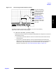
When using the 230-kHz IF filter, the Base Station must not be transmitting another
signal within seven channel spacings (210 kHz) above or below the signal being
measured; otherwise the measurement will be in error. In Figure 5-18, the Spectrum
Analyzer and delta marker functions are used to illustrate that another signal could
interfere with the measurement. (See the Reference Guide for information on using
the Spectrum Analyzer).
It is preferable to use the 230-kHz filter when possible. However, if it is not possible
to turn off a transmitter that is within 210 kHz of the signal to be measured, use the
narrow (30-kHz) filter.