Agilent Technologies Low-Profile Modular Power System Series N6700 User’s Guide A
Legal Notices © Agilent Technologies, Inc. 2006-2008 No part of this document may be photocopied, reproduced, or translated to another language without the prior agreement and written consent of Agilent Technologies, Inc. as governed by United States and international copyright laws. Warranty The material contained in this document is provided “as is,” and is subject to being changed, without notice, in future editions.
Safety Notices The following general safety precautions must be observed during all phases of operation of this instrument. Failure to comply with these precautions or with specific warnings or instructions elsewhere in this manual violates safety standards of design, manufacture, and intended use of the instrument. Agilent Technologies assumes no liability for the customer's failure to comply with these requirements. General Do not use this product in any manner not specified by the manufacturer.
In this Book Specific chapters in this manual contain the following information: Quick Reference – Chapter 1 is a quick reference section that helps you quickly become familiar with your Agilent N6700 Modular Power System. It describes the differences between the various modules in the power system. Installation – Chapter 2 describes how to install your power system. It describes how to connect various loads to the output. It discusses remote sensing as well as parallel and series operation.
Contents 1 - Quick Reference...............................................................................................................................7 The Agilent N6700 Modular Power System – At a Glance.......................... 8 The Front Panel - At a Glance......................................................................... 10 The Rear Panel – At a Glance......................................................................... 10 Front Panel Display – At a Glance .............................
Appendix A - Specifications ..............................................................................................................75 Agilent Models N6751A/N6752A, N6753A/N6754A, N6761A/N6762A 76 Agilent Models N6731B - N6736B and N6741B - N6746B........................ 82 Agilent Models N6773A - N6776A................................................................. 84 Agilent N6700B, N6701A, N6702A MPS Mainframes................................ 86 Appendix B - Using the Digital Port................
1 Quick Reference The Agilent N6700 Modular Power System – At a Glance.......................... 8 The Front Panel - At a Glance......................................................................... 10 The Rear Panel – At a Glance......................................................................... 10 Front Panel Display – At a Glance ................................................................. 11 Front Panel Keys – At a Glance.....................................................................
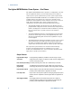
1 Quick Reference The Agilent N6700 Modular Power System – At a Glance The Agilent N6700 Modular Power System is a configurable, one rackunit (1U) platform that lets you mix and match power modules to create a power system optimized for your test system requirements. Agilent N6700–N6702 MPS mainframes are available in power levels of 400 W, 600 W, and 1,200 W. Up to four power modules can be installed in each mainframe.
Quick Reference 1 Output On/Off sequencing A turn-on/turn-off delay capability for each output allows output on/off sequencing. Remote voltage sensing Two remote sensing terminals are provided for each output. When shipped, the remote sense jumpers are included in a separate bag. See Chapter 2. Voltage and current measurements All power modules can measure their own output voltage and current.
1 Quick Reference The Front Panel - At a Glance Navigation keys Move the cursor to a menu item. Select the highlighted menu item. Display Turns off after 1 hour of inactivity. Press any key to restore the display. N6700A Modular Power System 20.007V o - 1 CV 4.004A Set: 20.000V 5.500A Meter Menu Channel Back Help Error Output keys Turn the outputs on or off. Enter voltage or current. On/Off Sel Voltage Current 7 8 9 4 5 6 1 2 3 0 .
Quick Reference 1 Front Panel Display – At a Glance Single-channel view Voltage measurement Bar indicates output polarity is reversed Current measurement Press the Meter key to toggle between views Operating status (CV = constant voltage) Multiple-channel view Voltage and current settings Interface status (IO = activity on interface) Voltage and Current measurements Press the Meter key to toggle between views The highlighted channel is the active channel Grouped-channel view Channels 2 through
1 Quick Reference Operating status indicators OFF = the output is off CV = the output is in constant voltage mode CC = the output is in constant current mode OV = the output is disabled by the over-voltage protection OC = the output is disabled by the over-current protection PF = the output is disabled by a power-fail condition CP+ = the output is limited (or disabled) by the positive power limit* OT = the over-temperature protection has tripped CP– = the output is limited by the negative power limit* INH
Quick Reference 1 Front Panel Menu Reference NOTE Menu commands that are grayed-out are either not available for the power module, or are password protected. Refer to the Service Guide for information about front panel menu commands prior to firmware revision B.00.00. Menu Command Control Description Output Voltage Programs voltage setting and range. Current Programs current setting and range. Delay Programs Turn-on /Turn off delay. Slew Programs voltage slew rate.
1 Quick Reference Menu Command System IO Control Description USB Status Displays status, speed, packets received, and packets sent. Identification USB connect string - the instrument’s unique USB identifier. GPIB DigPort Selects the GPIB address. Pin1 Function Polarity Specifies the pin function: DigIn, DigIO, TrigIn, TrigOut, FaultOut. Specifies the pin polarity: Positive, Negative Pin2 Function Polarity Specifies the pin function: DigIn, DigIO, TrigIn, TrigOut.
Quick Reference 1 SCPI Command Summary Subsystem Commands NOTE Some [optional] commands have been included for clarity. All settings commands have a corresponding query. Not all commands apply to all models.
1 Quick Reference SCPI Command OUTPut [:STATe] [,NORelay], (@chanlist) :COUPle[:STATe] :CHANNel [ {,}] :DOFFset :MAX:DOFFset? :DELay :FALL , (@chanlist) :RISE , (@chanlist) :PMODe VOLTage | CURRent, (@chanlist) :INHibit:MODE LATChing | LIVE | OFF :PON:STATe RST | RCL0 :PROTection :CLEar (@chanlist) :COUPle :DELay , (@chanlist) :RELay:POLarity NORMal | REVerse, (@chanlist) SENSe :CURRent [:DC]:RANGe [:UPPer] , (@chanlist) CCOMpensate , (@ch
Quick Reference SCPI Command [SOURce:]LIST (continued) :STEP ONCE | AUTO, (@chanlist) :TERMinate:LAST , (@chanlist) :TOUTput :BOSTep[:DATA] {,}, (@chanlist) :POINts? (@chanlist) :EOSTep[:DATA] {,}, (@chanlist) :POINts? (@chanlist) :VOLTage[:LEVel] {,}, (@chanlist) :POINts? (@chanlist) POWer:LIMit , (@chanlist) STEP:TOUTput , (@chanlist) VOLTage [:LEVel] [:IMMediate][:AMPLitude] , (@chanlist) :TRIGgered [:AMPLitude] , (@chanlist) :MODE FIXed
1 Quick Reference SCPI Command Description TRIGger :ACQuire [:IMMediate] (@chanlist) :SOURce BUS | PIN | TRAN, (@chanlist) :TRANsient [:IMMediate] (@chanlist) :SOURce BUS | PIN | TRAN, (@chanlist) (Acquire commands only on Agilent N6761A/62A and Option 054) Triggers the measurement immediately Sets the measurement trigger source Triggers the output immediately Sets the output trigger source Common Commands Command Description Command Description *CLS Clear status *RST Reset *ESE
2 Installation General Information.......................................................................................... 20 Inspecting the Unit ........................................................................................... 21 Installing the Unit.............................................................................................. 21 Connecting the Line Cord ................................................................................ 24 Connecting the Outputs.....................
2 Installation General Information Models Agilent Model N6700B / N6701A / N6702A N6751A / N6752A N6753A / N6754A N6761A / N6762A N6731B / N6741B N6732B / N6742B N6733B / N6743B / N6773A N6734B / N6744B / N6774A N6735B / N6745B / N6775A N6736B / N6746B / N6776A Description 400 W / 600 W / 1200W MPS Mainframe - without DC Power Modules 50 W / 100 W High-Performance Autoranging DC Power Module 300 W 20V / 60V High-Performance Autoranging DC Power Module 50 W / 100 W Precision DC Power Module 50 W / 100 W 5
Installation 2 Inspecting the Unit When you receive your power system, inspect it for any obvious damage that may have occurred during shipment. If there is damage, notify the shipping carrier and nearest Agilent Sales and Support Office immediately. Refer to www.agilent.com/find/assist. Until you have checked out the power system, save the shipping carton and packing materials in case the unit has to be returned.
2 Installation Tools required: Phillips driver, T22 Torx driver, T10 Torx driver Step 1. Install eight clip-nuts on the rack frame (2 in each corner) where your instrument will be located. Step 2. Install the two front ears and the two rear extender supports on the instrument as shown in the figure. Use six M3 x 8mm screws (a) for the front ears and four M3 x 6mm screws (b) for the extender supports. If the standard extender supports are either too short or too long, use the longer supports (c).
Installation 2 Bench Installation Do not block the air intake and exhaust at the sides, or the exhaust at the rear of the unit. Refer to the outline diagram in Appendix A. Minimum clearances for bench operation are 2 inches (51 mm) along the sides and back. Channel Number The channel number of a power module is determined by the location of that module in the mainframe. When viewed from the rear, the module next to the GPIB connector is always output channel one.
2 Installation Connecting the Line Cord WARNING FIRE HAZARD Use only the power cord that was supplied with your instrument. Using other types of power cords may cause overheating of the power cord, resulting in fire. SHOCK HAZARD The power cord provides a chassis ground through a third conductor. Be certain that your power outlet is of the three-conductor type with the correct pin connected to earth ground. Connect the power cord to the IEC 320 connector on the rear of the unit.
Installation 2 Connecting the Outputs WARNING SHOCK HAZARD Turn off AC power before making rear panel connections. All wires and straps must be properly connected with the terminal block screws securely tightened. Disconnect the connector plug to make your wire connections. The 12A connector plug accepts wires sizes from AWG 12 to AWG 30. The 20A connector plug accepts wires sizes from AWG 10 to AWG 24. The 50A connector plug accepts wires sizes from AWG 6 to AWG 20.
2 Installation Wire Size WARNING FIRE HAZARD Select a wire size large enough to carry short-circuit current without overheating. To satisfy safety requirements, load wires must be heavy enough not to overheat while carrying the short-circuit output current of the unit (refer to the following table). Along with conductor temperature, you must also consider voltage drop when selecting wire sizes.
Installation 2 Multiple Loads If you are using local sensing and are connecting multiple loads to one output, connect each load to the output terminals using separate connecting wires as shown in the following figure.
2 Installation Protecting Sensitive Loads from AC Power Switching Transients NOTE This only applies if you are connecting loads that are highly sensitive to voltage or current transients to the output of the modular power system. If your load is connected directly to the output of the power system and is not connected to chassis ground in any way, you do not need to worry about AC power switching transients appearing at the output of the modular power system.
Installation 2 Remote Sense Connections WARNING SHOCK HAZARD Turn off AC power before making or changing rear panel connections. Remote sensing improves the voltage regulation at the load by monitoring the voltage there instead of at the output terminals. This allows the power system to automatically compensate for the voltage drop in the load leads. Remote sensing is especially useful for CV operation with load impedances that vary or have significant lead resistance.
2 Installation Open Sense Leads The sense leads are part of the output's feedback path. Connect them in such a way so that they do not inadvertently become open circuited. The power system includes protection resistors that reduce the effect of open sense leads during remote-sensing operation. If the sense leads open during operation, the power system returns to the local sensing mode, with the voltage at the output terminals approximately 1% higher than the programmed value.
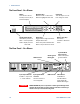
Installation OUTPUT 2 +S + OUTPUT 1 +S -S + TWIST LEADS SENSE JUMPERS INSTALLED OUTPUT 2 -S +S + 2 OUTPUT 1 +S -S + -S TWIST LEADS SENSE JUMPERS INSTALLED + + LOAD LOAD WITH LOCAL SENSING WITH REMOTE SENSING The following figure shows the connections for 50A power modules.
2 Installation On mainframes with earlier version firmware, first program both outputs to the desired output voltage. Then program the current limit point of each output. The current limit of the paralleled outputs will be the sum of both individual current limit points. Effect on Specifications Specifications for outputs operating in parallel can be obtained from the specifications for single outputs. Most specifications are expressed as a constant or as a percentage (or ppm) plus a constant.
Installation OUTPUT 2 +S + OUTPUT 1 +S -S + +S + +S -S + -S SENSE JUMPER INSTALLED SENSE JUMPERS INSTALLED SENSE JUMPERS INSTALLED OUTPUT 1 OUTPUT 2 -S 2 TWIST LEADS TWIST LEADS + + LOAD LOAD WITH LOCAL SENSING WITH REMOTE SENSING The following figure shows the connections for 50A power modules.
2 Installation Effect on Specifications Specifications for outputs operating in series can be obtained from the specifications for single outputs. Most specifications are expressed as a constant or a percentage (or ppm) plus a constant. For series operation, the percentage portion remains unchanged while constant portions or any constants are changed as indicated.
3 Getting Started Turning the Unit On .......................................................................................... 36 Selecting an Output Channel .......................................................................... 36 Entering an Output Voltage Setting ............................................................... 36 Entering a Current Limit Setting..................................................................... 37 Enabling the Output................................................
3 Getting Started Turning the Unit On After you have connected the line cord, turn the unit on with the front panel power switch. The front panel display will light up after a few seconds. A power-on self-test occurs automatically when you turn the unit on. This test assures you that the instrument is operational. If the selftest fails, the front panel Err indicator comes on. Press the Error key to display the list of errors on the front panel. Refer to the Service Guide for further information.
Getting Started 3 Entering a Current Limit Setting Method 1 – Use the Navigation and Arrow Keys Navigation Keys Use the left and right navigation keys to navigate to the setting that you wish to change. In the display below, channel 1’s current setting is selected. Enter a value using the numeric keypad. Then press Enter. Sel Arrow Keys © ª You can also use the arrow keys to adjust the value up or down.
3 Getting Started Using the Front Panel Menu The front panel command menu lets you access most of the power system’s functions. The actual function controls are located at the lowest menu level. Briefly: Press the Menu key to access the command menu. Press the navigation keys to move across the menu commands. Press the center (Sel) key to select a command and move down to the next level in the menu. Press the Help key at the lowest menu level to display help information about the function controls.
Getting Started Sel 4 3 The command menu is now at the function control level. This is the lowest level in this path. Use the navigation keys to highlight the OVP Level control as shown below. Enter the desired over-voltage level using the numeric keypad. Then press Enter. 4 Enter Channel NOTE Press the Channel key at any time to select a different output channel. This can save time because you can directly access the OVP control of each channel without having to navigate through the menu levels.
3 Getting Started Connecting to the Interfaces CAUTION Electrostatic discharges greater than 1 kV near the interface connectors may cause the unit to reset and require operator intervention. The Agilent N6700 MPS supports GPIB, LAN, and USB interfaces. All three interfaces are live at power-on. The front panel IO indicator comes on whenever there is activity on the remote interfaces.
Getting Started 3 USB Interface NOTE For detailed information about USB interface connections, refer to the Agilent Technologies USB/LAN/GPIB Interfaces Connectivity Guide, located on the Automation-Ready CD that is shipped with your product. The following steps will help you quickly get started connecting your USB-enabled instrument to the Universal Serial Bus (USB). The following figure illustrates a typical USB interface system. USB Cable PC Connect to USB port on PC.
3 Getting Started Connecting to a Site LAN A site LAN is a local area network in which LAN-enabled instruments and computers are connected to the network through routers, hubs, and/or switches. They are typically large, centrally-managed networks with services such as DHCP and DNS servers. To Network Interface Card (NIC) To LAN Port To Site LAN PC NOTE 1 If you have not already done so, install the Agilent IO Libraries Suite from the Automation-Ready CD that is shipped with your product.
Getting Started To Network Interface Card (NIC) PC NOTE Instrument 2 Connect the instrument to the computer using a LAN crossover cable. Alternatively, connect the computer and the instrument to a standalone hub or switch using regular LAN cables. Make sure your computer is configured to obtain its address from DHCP and that NetBIOS over TCP/IP is enabled. Note that if the computer had been connected to a site LAN, it may still retain previous network settings from the site LAN.
3 Getting Started LAN Parameters Viewing the Currently Active LAN Settings To view the currently active LAN settings, press the Menu key, then use the navigation keys to select: System\IO\LAN\ActiveSettings. The currently active settings for the IP Address, Subnet Mask, and Default Gateway may be different from the front panel configuration menu settings - depending on the configuration of the network. If the settings are different, it is because the network has automatically assigned its own settings.
Getting Started IP Address Subnet Mask Default Gateway 3 This value is the Internet Protocol (IP) address of the instrument. An IP address is required for all IP and TCP/IP communications with the instrument. An IP Address consists of 4 decimal numbers separated by periods. Each decimal number ranges from 0 through 255. This value is used to enable the instrument to determine if a client IP address is on the same local subnet.
3 Getting Started DNS Select DNS to configure the Domain Name System (DNS) setup of the instrument. DNS is an internet service that translates domain names into IP addresses. It is also needed for the instrument to find and display its hostname assigned by the network. Obtain DNS server from DHCP Select this item to obtain the DNS server address from DHCP. You must have enabled DHCP in the IP menu.
Getting Started 3 Using the Web Server Your power system has a built-in Web server that lets you control it directly from an internet browser on your computer. With the Web server, you can access the front panel control functions including the LAN configuration parameters. Up to two simultaneous connections are allowed. With additional connections, performance will be reduced. NOTE The built-in Web server only operates over the LAN interface. It requires Internet Explorer 6+, Netscape 6.
3 Getting Started Using Telnet In an MS-DOS Command Prompt box type: telnet hostname 5024 where hostname is the N6700 hostname or IP address, and 5024 is the instrument’s telnet port. You should get a Telnet session box with a title indicating that you are connected to the power system. Type the SCPI commands at the prompt. Using Sockets NOTE Power system mainframes with firmware revision C.00.
Getting Started 3 Securing the Interfaces Enable/Disable the USB, LAN, and Web Server The USB interface, LAN interface, and the Web server are enabled when shipped. To enable or disable the USB interface from the front panel, press the Menu key and select System\Admin\USB. Enable USB Check this box to enable the USB. Uncheck this box to disable the USB. To enable or disable the LAN interface or Web server, press the Menu key and select the following menu commands: System\Admin\LAN.
3 Getting Started Factory-shipped non-volatile LAN settings Get IP Address Automatic Dynamic DNS naming service Enabled IP Address Subnet Mask 169.254.67.0 NetBIOS naming service Enabled 255.255.0.0 Domain name Blank Default Gateway 0.0.0.
4 Operating the Power System Programming the Output ................................................................................. 52 Synchronizing Output Steps............................................................................ 55 Making Measurements.................................................................................... 58 Using the Protection Functions ...................................................................... 59 System-Related Operations................................
4 Operating the Power System Programming the Output Select an Output Channel Front Panel: SCPI Command: Press the Channel key to select an output channel. Enter the selected channel(s) in the command’s parameter list. (@1,2) Set the Output Voltage Front Panel: SCPI Command: Press the Voltage key. To set output 1 to 5 V: VOLT 5,(@1) To set all outputs to 10 V: VOLT 10,(@1:4) Enter a value and press Select.
Operating the Power System 4 Set the Output Current Front Panel: SCPI Command: Press the Current key. To set output 1 to 1 A: CURR 1,(@1) To set all outputs to 2 A: CURR 2,(@1:4) Enter a value and press Select. For models with multiple ranges, you can select a lower range if you need better output resolution. Front Panel: SCPI Command: Press the Current key. To select the lower range, program a value that falls within the range: CURR:RANG 1,(@1) Select a lower range and press Select.
4 Operating the Power System Output channel turn-on characteristics vary across the three module types - DC Power, Autoranging, and Precision (Refer to Appendix D for more information). When output channels of the same module type are programmed off-to-on, output sequencing is precisely determined by the programmed turn-on delays. When outputs of different module types are sequenced, there may be an additional offset of a few milliseconds from one output to another.
Operating the Power System 4 Synchronizing Output Steps The transient system lets you step the output voltage and current up or down in response to triggered events. To generate a triggered output step you must: 1. Enable the output to respond to trigger commands. 2. Set the voltage or current trigger levels. 3. Select the transient trigger source. 4. Initiate the trigger system and provide a trigger signal.
4 Operating the Power System Select the Transient Trigger Source NOTE An immediate trigger command either from the front panel or over the bus will generate an immediate trigger regardless of the trigger source. Unless you are using the front panel menu or a TRIG:TRAN command to trigger the output, select a trigger source from the following: Bus Selects GPIB device trigger, *TRG, or (Group Execute Trigger). Pin Selects a pin on the external port connector as the trigger source.
Operating the Power System 4 Trigger the Output The trigger system is waiting for a trigger signal in the initiated state. You can immediately trigger the output as follows: Front Panel: SCPI Command: Select Transient\Control. To generate an immediate trigger on channel 1: TRIG:TRAN (@1) Select Trigger to generate an immediate trigger signal regardless of the trigger source setting.
4 Operating the Power System Making Measurements Each output channel has its own measurement capability. The output voltage and current is measured by acquiring a number of samples at the selected time interval, applying a window function to the samples, and averaging the samples. The power-on and *RST time interval and number of samples settings yield a measurement time of 21 milliseconds per reading (1024 data points at 20.48 μs intervals). The output windowing function is Rectangular.
Operating the Power System 4 Using the Protection Functions Each output has independent protection functions. A front panel status indicator will turn on when a protection function has been set. Protection functions are latching, which means that they must be cleared once they have been set. As explained under “Couple Output Protection” you can configure the instrument so that when a protection fault occurs on one output, ALL outputs will be turned off.
4 Operating the Power System You can also specify a delay to prevent momentary CV-to-CC status changes from tripping the over-current protection. Front Panel: SCPI Command: Select Protect\OCP. To specify a 10 millisecond delay: OUTP:PROT:DEL 0.01,(@1,2) Enter a delay value and press Select. Check "Start delay on CC" to start the delay timer by ANY output transition into CC mode. Otherwise, the delay timer will only be started by a settings change in voltage, current, or output state.
Operating the Power System 4 System-Related Operations Self-Test A power-on self-test occurs automatically when you turn on the power system. This test assures you that the instrument is operational. If the self-test is successful, the power system will continue to operate normally. If the self-test fails, the front panel Err indicator comes on. Press the Error key to display the list of errors on the front panel. Refer to the Service Guide for further information. Front Panel: Cycle AC power.
4 Operating the Power System Output Groups NOTE The ability to group outputs is only available on power system mainframes with firmware revision B.00.00 and up. Output channels can be configured or “grouped” to create a single output with higher current and power capability. Almost all instrument functionality is supported by grouped channels, including voltage and current programming, measurements, status, step and list transients.
Operating the Power System 4 Front Panel Keys Lockout NOTE The ability to lock the front panel from the front panel is only available on power system mainframes with firmware revision B.00.00 and up. You can lock the front panel keys to prevent unwanted control of the instrument from the front panel. This is the most secure way of locking the front panel keys because you need a password to unlock the front panel.
4 Operating the Power System Front Panel Display Screen Saver The power system has a front panel screen saver that significantly increases the life of the LCD display by turning it off during periods of inactivity. As shipped from the factory, the screen saver comes on one hour after activity on the front panel or interface has ceased. When the screen saver is active, the front panel display turns off, and the LED next to the Line switch changes from green to amber.
Operating the Power System 4 Programming High-Speed Test Extensions NOTE The High-Speed Test Extensions described in this section are not available on all models (Refer to Chapter 1, “Model Differences”). The List Function Either output voltage or output current, or both together, may be listcontrolled. List mode lets you generate complex sequences of output changes with rapid, precise timing, which may be synchronized with internal or external signals.
4 Operating the Power System Program an Output Pulse or Pulse Train The following procedure shows how to generate an output pulse train using the List function. Trigger 0 Pulse width 1 Off time List Count = 1+additional pulses Step 1. Set the voltage or current function for which you want to generate a pulse to List mode. This example programs a voltage pulse. Front Panel: SCPI Command: Select Transient\Mode. Set the voltage mode to List. Press Select.
Operating the Power System 4 Step 5. To generate a pulse train, you can simply repeat the pulse as needed. For example, to program a pulse train of 50 pulses, use: Front Panel: SCPI Command: Select Transient\List\Repeat. To program output 1, use LIST:COUN 50, (@1) Enter the number of list repetitions (50) and Press Select. Step 6.
4 Operating the Power System Program an Arbitrary List The following procedure shows how to generate the list of voltage changes as illustrated in the following figure. Trigger 0 1 2 3 4 5 List Count = 1 List Count = 2 Step 1. Set the function, voltage or current, for which you want to generate a list to List mode. This example programs a voltage list. Front Panel: SCPI Command: Select Transient\Mode. Set the Voltage mode to List. Press Select.
Operating the Power System 4 Front Panel: Select Transient\List\Pace. SCPI Command: LIST:STEP AUTO, (@1) Select Dwell-paced. Press Select. In a trigger-paced list, the list advances one step for each trigger received. To enable trigger-paced lists, select Trigger-paced on the front panel menu. (Set the LIST:STEP command to ONCE.) The dwell time associated with each step determines the minimum time that the output remains at the step.
4 Operating the Power System The Digitizer Function The digitizer function lets you access the enhanced voltage and current measurement capabilities of the power system. You can: Adjust the measurement sample rate - to a maximum of 50 kHz. Adjust measurement triggers to capture pre-trigger transients. Select a measurement window that can attenuate AC noise. Retrieve arrays of the digitized current or voltage measurement. Synchronize measurements using trigger signals.
Operating the Power System 4 4096 DATA POINTS OFFSET = -4095 4096 DATA POINTS OFFSET = -2048 4096 DATA POINTS OFFSET = 0 OFFSET = 0 to 2 TIME 9 4096 DATA POINTS TRIGGER To offset the beginning of the acquisition buffer relative to the acquisition trigger, use: Front Panel: SCPI Command: Select Measure\Sweep. To offset the measurement on channel 1 by 100 points use: Enter an offset value and press Select.
4 Operating the Power System To select a window function, use: Front Panel: SCPI Command: Select Measure\Window. To set the sense window to Hanning for output 1 use: SENS:WIND HANN, (@1) Then select either Rectangular or Hanning and press Select. Retrieve Measurement Array Data Array queries return all values in the voltage and current measurement buffer. No averaging is applied, only raw data is returned from the buffer.
Operating the Power System 4 To trigger measurements on models that do not have simultaneous voltage and current measurement capability, select the measurement function as follows.
4 Operating the Power System Initiate the Measurement Trigger System Next, you must initiate or enable the measurement trigger system. When the power system is turned on, the trigger system is in the idle state. In this state, the trigger system is disabled, ignoring all triggers. The INITiate commands enable the measurement system to receive triggers.
Appendix A Specifications Agilent Models N6751A/N6752A, N6753A/N6754A, N6761A/N6762A 76 Agilent Models N6731B - N6736B and N6741B - N6746B........................ 82 Agilent Models N6773A - N6776A................................................................. 84 Agilent N6700B, N6701A, N6702A MPS Mainframes................................ 86 This chapter lists the specifications and supplemental characteristics of the Agilent N6700 Modular Power System.
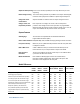
Appendix A Specifications Agilent Models N6751A/N6752A, N6753A/N6754A, N6761A/N6762A Performance Specifications N6751A / N6752A N6753A N6754A N6761A / N6762A DC Output Ratings: Voltage 50 V 20 V 60 V 50 V 5 A / 10A 50 A 20 A 1.5 A / 3 A 50 W / 100 W 300 W 300 W 50 W / 100 W CV peak-to-peak 4.5 mV 5 mV 6 mV 4.5 mV CV rms 0.35 mV 1 mV 1 mV 0.
Specifications Appendix A Supplemental Characteristics N6751A / N6752A N6753A N6754A N6761A / N6762A 20 mV – 51 V 10 mV – 20.4V 25 mV- 61.2V 15 mV – 51 V N/A N/A N/A 12 mV – 5.5 V 10 mA – 5.1A/10 mA- 10.2A 50 mA – 51A 20 mA- 20.4A 1 mA–1.53 A/1 mA–3.06 A N/A N/A N/A 0.1 mA – 0.1 A NOTE 1 3.5 mV 1.5 mV 4.2 mV 880 μV N/A N/A N/A 90 μV 3.25 mA 16.3 mA 6.5 mA 60 μA N/A N/A N/A 2 μA 1.8 mV 0.8 mV 2.2 mV 440 μV Programming Ranges: Voltage high range Voltage low range (≤ 5.
Appendix A Specifications Supplemental Characteristics (continued) N6751A / N6752A N6753A N6754A N6761A / N6762A 0 V to 10 V 0 V to 6 V 0 V to 15 V 0 V to 10 V 0.2 ms 0.4 ms 0.35 ms 0.6 ms 0 V to 50 V 0 V to 20 V 0 V to 60 V 0 V to 50 V 1.5 ms 1.5 ms 2 ms 2.
Specifications Appendix A Autoranging Characteristic Autoranging 50 W Output Voltage Voltage 50 V Autoranging 100 W Output Voltage 50 W curve Current 0 1A 50 V 100 W curve 300 W curve Precision Outputs 50 W & 100 W 33 V 15 V 6V 12 V 8.5 V Current 0 5A Voltage 60 V 20 V 50 V 10 V Autoranging 300 W Output 2A Current Current 0 8.33 A 10 A 5A 15 A 0 20 A 50 A 1 A 1.
Specifications 80 135 90 40 90 45 20 40 20 Phase 10 5 2.5 0 10 -45 5 -90 2.5 1.25 1.25 0.62 0.62 -45 1k 10k FREQUENCY (Hz) 100 100k 1k 10k FREQUENCY (Hz) 100k Model N6753A, Option 760, CV Mode, @20V, 15A Model N6753A, CV Mode, @20V, 15A 0.8 0.8 Magnitude Magnitude IMPEDANCE (ohms) 0 Magnitude Magnitude 100 45 Phase 0.4 0.4 Phase Phase 90 45 0.2 45 0.1 0 0.1 0 0.05 -45 0.05 -45 0.025 -90 0.025 -90 0.0125 -135 0.0125 0.0062 0.0062 0.
Specifications 90 0.4 90 0.2 45 0.2 45 0.1 0 0.1 0 -45 0.05 0.05 Phase Phase -90 0.025 0.025 Magnitude 0.0125 -45 -90 Magnitude 0.0125 0.0062 0.0062 100 1k 10k FREQUENCY (Hz) 1k 100 100k 10k 100k FREQUENCY (Hz) Model N6754A, Option 760, CV Mode, @60V, 5A Model N6754A, CV Mode, @60V, 5A 8 8 Magnitude Magnitude 4 4 45 2 Phase 45 2 Phase 0 0 1 0.5 -45 0.5 -45 0.25 -90 0.25 -90 0.125 -135 0.125 -135 0.062 0.
Appendix A Specifications Agilent Models N6731B - N6736B and N6741B - N6746B Performance Specifications N6731B/ N6741B N6732B/ N6742B N6733B/ N6743B N6734B/ N6744B N6735B/ N6745B N6736B/ N6746B 5V 8V 20 V 35 V 60 V 100 V DC Output Ratings: Voltage NOTE 2 Current NOTE 1 Power 10 A / 20 A 6.25 A / 12.5 A 2.5 A / 5 A 1.5 A / 3 A 0.8 A / 1.6 A 0.5 A / 1 A 50 W / 100 W 50 W / 100 W 50 W / 100 W 52.
Specifications Appendix A Supplemental Characteristics N6731B/ N6741B N6732B/ N6742B N6733B/ N6743B N6734B/ N6744B N6735B/ N6745B N6736B/ N6746B Voltage 15 mV – 5 .1 V 15 mV – 8 .16 V 30 mV – 20.4 V 40 mV – 35.7 V 70 mV – 61.2 V 100 mV – 102 V Current 60 mA – 10.2 A/ 60 mA – 20.4 A 40 mA –6.375 A/ 40 mA – 12.75 A 10 mA – 2.55 A/ 10 mA – 5.1 A 5 mA – 1.53 A/ 5 mA – 3.06 A 2.5mA – 0.85 A/ 2.5m A – 1.7 A 1.5 mA – 0.51A/ 1.5 mA – 1.
Appendix A Specifications Agilent Models N6773A - N6776A Performance Specifications N6773A N6774A N6775A N6776A DC Output Ratings: Voltage 20 V 35 V 60 V 100 V 15 A NOTE 2 8.
Specifications Appendix A Supplemental Characteristics N6773A N6774A N6775A N6776A Programming Ranges: Voltage 30 mV – 20.4 V 40 mV – 35.7 V 70 mV – 61.2 V 100 mV – 102 V Current 30 mA – 15.3 A 15 mA – 8.67 A 7.5 mA – 5.1 A 4.5 mA – 3.06 A Voltage 7 mV 10 mV 18 mV 28 mV Current 9 mA 6 mA 3 mA 1.5 mA Voltage 10 mV 18 mV 30 mV 50 mV Current 9 mA 6 mA 3 mA 1.5 mA Programming Resolution: Measurement Resolution: Temperature Coefficient per °C: Voltage Programming 0.01% + 0.
Appendix A Specifications Agilent N6700B, N6701A, N6702A MPS Mainframes Supplemental Characteristics N6700B, N6701A, N6702A Command Processing Time: ≤ 1 ms from receipt of command to start of output change Protection Response Characteristics: INH input 5 µs from receipt of inhibit to start of shutdown Fault on coupled outputs < 10 µs from receipt of fault to start of shutdown Digital Control Characteristics: Maximum voltage ratings +16.
Specifications Appendix A Supplemental Characteristics (continued) N6700B, N6701A, N6702A Environmental Conditions Operating environment Indoor use, installation category II (for AC input), pollution degree 2 Temperature range 0°C to 55°C (output current is derated 1% per °C above 40°C ambient temperature) Relative humidity Up to 95% Altitude Up to 2000 meters Storage temperature -30°C to 70°C LED statement Any LEDs in this unit are Class 1 LEDs as per IEC 825-1 Acoustic Noise Declaration: Thi
Appendix A Specifications Outline Diagram 549.7 mm 21.64" N6700B/ N6701A 560.2 mm 22.06" N6700B/ N6701A 598.0 mm 23.54" N6702A 608.5 mm 23.96" N6702A 25.4 mm 1.00" 432.5 mm 17.03" 482.6 mm 19.00" 44.45 mm 1.75" = AIRFLOW . 425.45 mm 16.
Appendix B Using the Digital Port Digital Control Port ........................................................................................... 90 Configuring the Digital Control Port............................................................... 91 A Digital Control Port consisting of seven I/O pins is provided to access various control functions. Each pin is user-configurable.
Appendix B Using the Digital Port Digital Control Port An 8-pin connector and a quick-disconnect connector plug are provided on each instrument for accessing the five digital control port functions. TIGHTEN SCREWS 1 2 3 4 5 6 7 I + INSERT WIRES Output trigger signal, or Input trigger signal Signal Common The digital control connector accepts wires sizes from AWG 14 to AWG 30. Note that wire sizes smaller than AWG 24 are not recommended.
Using the Digital Port Appendix B Configuring the Digital Control Port Bi-directional Digital I/O Each of the seven pins can be configured as general purpose bidirectional digital inputs and outputs. The polarity of the pins can also be configured. Pin 8 is the signal common for the digital I/O pins.
Appendix B Using the Digital Port Digital Input Each of the seven pins can be configured as digital input only. The polarity of the pins can also be configured. Pin 8 is the signal common for the digital input pins. The pin status reflects the true condition of the external signal that is applied to the pin. The pin state is not affected by the value of the digital output word.
Using the Digital Port Appendix B Fault Output Pins 1 and 2 can be configured as a fault-output pair. The polarity of pin 1 can also be configured. Pin 1 is the Fault output; pin 2 is the common for pin 1. Note that pin 2 must also be connected to pin 8. The Fault Output function enables a fault condition on any channel to generate a fault signal on the Digital Control port.
Appendix B Using the Digital Port Fault/Inhibit System Protection The following figure illustrates some ways that you can connect the Fault/Inhibit pins of the connector.
Appendix C Power Allocation Power Limit Operation ..................................................................................... 96 Module Power Allocation ................................................................................ 97 This chapter discusses the power allocation function. For the majority of Agilent N6700 Modular Power System configurations, full power is available from all installed power modules.
Appendix C Power Allocation Power Limit Operation Mainframe Power Limit If the combined power drawn from all of the power modules exceeds the mainframe’s power rating, a power fault protection event will occur. This causes ALL outputs to turn off and remain off until a protection clear command is given. This is explained in chapter 4 under “Clear Output Protection Functions”. A status bit (PF) will indicate that a power fault protection event has occurred.
Power Allocation Appendix C Module Power Allocation The following commands program the module power limit function: Front Panel: SCPI Command: Select Output\Power. To set a power limit on output 1: POW:LIM 100,(@1) Enter a power limit for each output. To query the power limits that are set, send: Front Panel: Select Output\Power. SCPI Command: POW:LIM? (@1:4) The power allocation for all output channels is displayed in the dialog boxes.
Appendix D Output On/Off Synchronization Synchronizing Output Turn-on Delays.........................................................100 Synchronizing Multiple Mainframes............................................................103 Operation ..........................................................................................................104 This chapter discusses output on/off synchronization.
Appendix D Output On/Off Synchronization Synchronizing Output Turn-on Delays Tutorial All N6700 Power Modules that are installed in an Agilent N6700 mainframe exhibit a minimum delay offset that applies from the time that a command to turn on the output is received until the output actually turns on. If you specify a user-programmed turn-on delay, this delay will be added to the minimum delay offset, resulting in a turn-on delay that is actually longer than the one you programmed.
Output On/Off Synchronization Appendix D By setting the common delay offset to be greater than or equal to the largest minimum delay offset, you can synchronize the programmed turn-on delays as shown in the following example.
Appendix D Output On/Off Synchronization 2. Specify which Output Channels will be Synchronized Select the output channels that will be synchronized. Front Panel: SCPI Command: In the front panel menu, select To specify a channel or channels: OUTP:COUP:CHAN 1,2,3,4 Output\Couple. Check which channels will be coupled. To remove a channel, uncheck the box. 3. Specify the Turn-On Delays for each Output Channel Turn-on delays can be specified for all coupled output channels.
Output On/Off Synchronization Appendix D Synchronizing Multiple Mainframes The output turn-on synchronization function can be used across multiple mainframes that have coupled output channels. Each mainframe that will be synchronized must have at least one coupled channel. Note that cross-frame synchronization must be enabled for any mainframe that contains synchronized output channels. Procedure 1.
Appendix D Output On/Off Synchronization Mainframe #1 1 2 3 4 5 6 Mainframe #2 7 I 1 2 3 4 5 6 Mainframe #3 7 I 1 2 3 4 5 6 7 I ON Couple OFF Couple Common Only two of the digital connector pins on each mainframe can be configured as “ONCouple” and “OFFCouple” on each synchronized mainframe. The designated pins will function as both an input and an output, with a negative transition on one pin providing the synchronization signal to the other pins.
Index A Admin menu, password ................................................... 49 airflow..................................................................... 21, 23, 88 All ...................................................................................11, 53 allocation, power ............................................................... 96 autoranging, characteristic.............................................. 79 B bench location....................................................................
Index H Hanning ............................................................................... 71 Help................................................................................38, 39 history.................................................................................... 2 I INH ....................................................................................... 12 inhibit input configuring ..................................................................... 93 connections ....................
Index protection, clearing ........................................................... 60 protection, coupling .......................................................... 60 protection, functions......................................................... 59 pulse .................................................................................... 66 R rack mounting .................................................................... 21 tools required.............................................................
DECLARATION OF CONFORMITY According to ISO/IEC Guide 22 and CEN/CENELEC EN 45014 Responsible Party Alternate Manufacturing Site Manufacturer’s Name: Agilent Technologies, Inc. Agilent Technologies (Malaysia) Sdn.
Manual Updates The following updates have been made to this manual since its publication date. 01/22/08 Information about the new 1-microampere measurement range (Option 1UA) for Agilent N6761A/N6762A power modules has been added to pages 20, 58, 76, and 77. Additional information about programming the over-current protection delay has been added to pages 59 and 60. The above changes apply to mainframes with firmware revision C.02.13 and higher.