
User's Manual
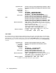
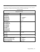
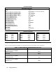
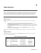
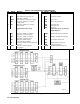
Table Of Contents
- TABLE OF CONTENTS
- Safety Summary
- Safety Symbols
- Acoustic Noise Info
- Declaration Page
- Printing History
- GENERAL INFORMATION
- INSTALLATION
- TURN-ON CHECKOUT
- USER CONNECTIONS
- FRONT PANEL OPERATION
- REMOTE PROGRAMMING
- LANGUAGE DICTIONARY
- STATUS REPORTING
- SPECIFICATIONS
- CALIBRATION
- VERIFICATION
- ERROR MESSAGES
- LINE VOLTAGE CONVERSION
- DIGITAL PORT FUNCTIONS
- COMPATIBILITY LANGUAGE
- INDEX
- Agilent Sales and Support Office
- Manual Updates
Status Reporting
88
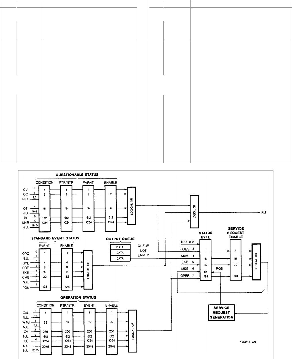
Table 8-2. Bit Configurations of Status Registers
Bit Signal Meaning Bit Signal Meaning
Operation Status Group Standard Event Status Group
0 CAL The interface is computing new
calibration constants.
0 OPC Operation complete.
5 WTG The interface is waiting for a trigger. 2 QYE Query error.
8 CV The power module is in constant
voltage mode.
3 DDE Device-dependent error.
10 CC The power module is in constant 4 EXE Execution error.
current mode. 5 CME Command error.
7 PON Power on.
Questionable Status Group Status Byte and Service Request
Enable Registers
0 OV The power module overvoltage
protection circuit has tripped.
3 QUES Questionable status summary bit.
1 OC The power module overcurrent
protection circuit has tripped.
4 MAV Message Available summary bit.
4 OT The power module has an
overtemperature condition.
5 ESB Event Status summary bit.
9 RI The power module remote inhibit state
is active.
6 MSS
RQS
Master Status summary bit.
Request Service bit.
10 UNR The power module output is
unregulated.
7 OPER Operation status summary bit.
Figure 8-1. Power supply Status Model