S Agilent 81130A 400/660MHz Pulse/Data Generator Reference Guide S1
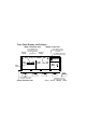
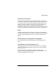
Front Panel Display and Softkeys Mode / Parameter Area Channel 1 Column Use the CURSOR keys to move the entry focus to a mode, parameter format, or parameter value ON OFF Delay DtyCyc 1 Modify / Enter Area Use the KNOB to select a mode or modify parameters and formats Channel 2 Column Freq 50.00MHz 0ps Delay 50.0% Width Press ENTER or a UNIT key to confirm parameter changes OFF OFF 2 0ps 100.0ns Entry Focus MODIFY 50.
Reference Guide Agilent 81130A 400/660 MHz Pulse/Data Generator Part No. 81130-91021 Printed in Germany March 2000 Edition 1.
Notice Notice Copyright 1998 Agilent Technologies 1998, 2000. All rights reserved. No part of this manual may be reproduced in any form or by any means (including electronic storage and retrieval or translation into a foreign language) without prior agreement and written consent from Agilent Technologies Inc. as governed by United States and international copyright laws. Notice The material contained in this document is subject to change without notice.
Notice Agilent Technologies warrants that its software and firmware designated by Agilent Technologies for use with an instrument will execute its programming instructions when properly installed on that instrument. Agilent Technologies does not warrant that the operation of the instrument software, or firmware, will be uninterrupted or error free.
Safety Summary Safety Summary The following general safety precautions must be observed during all phases of operation of this instrument. Failure to comply with these precautions or with specific warnings elsewhere in this manual violates safety standards of design, manufacture, and intended use of the instrument. Agilent Technologies Inc. assumes no liability for the customer's failure to comply with these requirements.
Safety Summary Ground the Instrument To minimize shock hazard, the instrument chassis and cover must be connected to an electrical protective earth ground. The instrument must be connected to the ac power mains through a grounded power cable, with the ground wire firmly connected to an electrical ground (safety ground) at the power outlet.
Safety Summary Safety Symbols Caution (refer to accompanying documents) Protective earth (ground) terminal In the manuals: WA RN I NG The WARNING sign denotes a hazard. It calls attention to a procedure, practice, or the like, which, if not correctly performed or adhered to, could result in personal injury. Do not proceed beyond a WARNING sign until the indicated conditions are fully understood and met. CA UT IO N The CAUTION sign denotes a hazard.
About this Book About this Book This guide provides reference information primarily for programming the Agilent 81130A via remote control. Chapter 1 General Programming Aspects on page 13 gives general hints for programming instruments like the Agilent 81130A using SCPI commands. Chapter 2 Programming Reference on page 25 provides detailed information on the SCPI commands supported by the instrument.
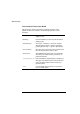
About this Book Conventions Used in this Book This book uses certain conventions to indicate elements of the Agilent 81130As user interface. The following table shows some examples: Softkeys Press the MODE/TRG softkey to access the Mode/ Trigger screen. Hardkeys Press the MORE key to switch to the alternative softkey layout. Alternate Keys Press SHIFT + 0 (ON/OFF1) to switch on output1. The alternate key labelwhich is selected by pressing the SHIFT keyis given in parentheses.
Contents Notice ......................................................................................... 4 Safety Summary ......................................................................... 6 About this Book ......................................................................... 9 Chapter 1 General Programming Aspects The GP-IB Interface Bus ......................................................... 14 Agilent 81130A Remote Control ............................................
Contents Agilent 81130A Specifications ............................................... 97 General ................................................................................................... 97 Timing Specifications ........................................................................... 99 Main Output Level Specifications ..................................................... 102 External Input, External Clock/PLL Reference Input .................... 103 Trigger Modes .............................
1 1General Programming Aspects This chapter provides general information on writing GP-IB/SCPI programs for instruments like the Agilent 81130A. Detailed information on programming the Agilent 81130A can be found in Chapter 2 Programming Reference on page 25.
General Programming Aspects The GP-IB Interface Bus The GP-IB Interface Bus The GP Interface Bus is the interface used for communication between a controller and an external device, such as the Agilent 81130A. The GP-IB conforms to IEEE standard 488-1987, ANSI standard MC 1.1, and IEC recommendation 625-1. If you are not familiar with the GP-IB, please refer to the following books: The Institute of Electrical and Electronic Engineers: IEEE Standard 488.
General Programming Aspects Agilent 81130A Remote Control Agilent 81130A Remote Control GP-IB Address You can only set the GP-IB address from the front panel of the instrument (refer to the Quick Start Guide). The default GP-IB address is 10. Modes of Operation The Agilent 81130A has two modes of operation: Local The instrument is operated using the front panel keys. Remote After receiving the first command or query via the GP-IB, the instrument is put into remote state. The front panel is locked.
General Programming Aspects Programming Recommendations Programming Recommendations Here are some recommendations for programming the instrument: Start programming from the default setting. The common command for setting the default setting is: *RST Switch off the automatic update of the display to increase the programming speed. The device command for switching off the display is: :DISPlay OFF The SCPI standard defines a long and a short form of the commands.
General Programming Aspects Programming Recommendations It is recommended to test a new setting that will be programmed on the instrument by setting it up manually. Enable the outputs so that the instruments error check system is on and possible parameter conflicts are immediately displayed. When you have found the correct setting, then use this to create the program. In the program it is recommended to send the command for enabling outputs (for example, :OUTPut ON) as the last command.
General Programming Aspects Common Command Summary Common Command Summary This table summarizes the IEEE 488.
General Programming Aspects Status Model Status Model QUESTIONABLE STATUS Voltage Warning Current Warning Timing Warning Frequency Warning Pattern Warning 0 1 2 3 4 5 6 7 8 9 15 OPERation Status (NOT USED) 0 1 2 3 4 5 6 7 8 9 Status Byte MAV SRQ 0 1 2 3 4 5 6 7 15 Standard Event Status Operation Complete 0 1 2 Query Error Device Dependent Error 3 Execution Error 4 Command Error 5 6 Power On 7 The instrument has a status reporting system conforming to IEEE 488.2 and SCPI.
General Programming Aspects Status Model Condition Register Transition Filters Event Register Enable Register OR Hardware and Firmware condition 1 0 PTR NTR Summary Bit 1 Latched 0 Condition Register A condition register contains the current status of the hardware and firmware. It is continuously updated and is not latched or buffered. You can only read condition registers. If there is no command to read the condition register of a particular status group, then it is simply invisible to you.
General Programming Aspects Status Model Enable Register The enable register defines which bits in an event register are included in the logical OR into the summary bit. The enable register is logically ANDed with the event register and the resulting bits ORed into the summary bit. Enable registers are read/write, and are not affected by *CLS or querying. Although all status groups have all of these registers, not all status groups actually use all of the registers.
General Programming Aspects Status Model Status Byte The status byte summarizes the information from all other status groups. The summary bit for the status byte actually appears in bit 6 (RQS) of the status byte. When RQS is set it generates an SRQ interrupt to the controller indicating that at least one instrument on the bus requires attention.
General Programming Aspects Status Model OPERation Status Group This Status Group is not used in the instrument.
General Programming Aspects Status Model QUEStionable Status Group Bit QUEStionable 0 Voltage warning 1 Current warning 2 Time warning 3 Unused, always 0 4 Unused, always 0 5 Frequency warning 6 Unused, always 0 7 Unused, always 0 8 Unused, always 0 9 Pattern warning 10 Unused, always 0 11 Unused, always 0 12 Unused, always 13 Unused, always 0 14 Unused, always 0 15 Always 0 The QUEStionable Status group is used to report warning conditions amongst the voltage, current, pu
2 2Programming Reference This chapter provides reference information on the following topics: Agilent 81130A SCPI Command Summary on page 26 Default Values, Standard Settings on page 34 Programming the Instrument Trigger Modes on page 38 SCPI Instrument Command List on page 42 For general programming information, please refer to Chapter 1 General Programming Aspects on page 13.
Programming Reference Agilent 81130A SCPI Command Summary Agilent 81130A SCPI Command Summary Command Parameter Description see page (Trigger mode and source) :ARM [:SEQuence[1] | :STARt] [:LAYer[1]] :LEVel [:THReshold] Set/read threshold level at EXT INPUT 43 :TERMination Set/read the termination voltage at EXT INPUT 43 :MODE GATed | STARted Set/read the trigger mode, if the source is not IMMediate 43 :SENSe POSitive | NEGative Set/read trigger on edge or gate on level
Programming Reference Agilent 81130A SCPI Command Summary Command Parameter Description see page :DIGital [:STIMulus] :PATTern 48 :LOOP 45 46 :INFinite [:STATe] ON | OFF | 1 | 0 Enables/Disables the infinite loop :STARt SEGM1 | SEGM2 | SEGM3 | SEGM4 Set/read the start of the infinite loop (the segment to restart the output after the last bit of the last used segment) [:COUNt] Set/read the segment loop count :STARt SEGM1 | SEGM2 | SEGM3 | SEGM4 Set/read the start segment for the c
Programming Reference Agilent 81130A SCPI Command Summary Command Parameter Description see page 55 :DISPlay [:WINDow] ON|OFF|1|0 Set/read frontpanel display state :CATalog? [A:] Read directory of memory card 56 :CDIRectory [] Change directory on memory card 56 :COPY [,A:], [,A: ] Copy a file on memory card 57 :DELete [,A:] Delete a file from memory card 57 :INITialize [A:[DOS]] Initialize memory card to DOS format 58 , Load file from memory ca
Programming Reference Agilent 81130A SCPI Command Summary Command Parameter Description see page [:SOURce] :CORRection[1|2] 60 :EDELay [:TIMe] Set/read channel delay deskew The CURRent and VOLTage subsystem cannot be used at the same time. Use the :HOLD command to select between them.
Programming Reference Agilent 81130A SCPI Command Summary Command Parameter Description see page [:SOURce] :PHASe[1|2] [:ADJust] Set/read channel phase :DCYCle[1|2] Set/read channel dutycycle 67 :DELay[1|2] Set/read channel delay (to leading edge) 68 :HOLD TIME|PRATio Hold absolute delay|delay as period fixed with varying frequency 69 :UNIT S|SEC|PCT|DEG| RAD Set/read delay units 70 :HOLD[1|2] WIDTh | DCYCle | TDELay Hold Width|Dutycycle|Trailing e
Programming Reference Agilent 81130A SCPI Command Summary Command Parameter Description see page INTernal|EXTernal Set/read PLL reference source 76 Set/read frequency of external PLL reference. Value will be rounded to 1 MHz, 2 MHz, 5 MHz or 10 MHz.
Programming Reference Agilent 81130A SCPI Command Summary Command Parameter Description see page :STATus 81 :OPERation [:EVENt]? Read Operation event register 81 :CONDition Read Operation condition register 81 :ENABle Numeric Set/Read Operation enable register 81 :NTRansition Numeric Set/Read Operation negative-transition register 81 :PTRansition Numeric Set/Read positive-transition register 81 Clear and preset status groups 82 :PRESet 82 :QUEStionable [:EVENt]? Read Questionab
Programming Reference Agilent 81130A SCPI Command Summary Command Parameter Description see page Read error queue 84 Simulate key press or read last key pressed 84 no function 87 :SYSTem :ERRor? :KEY Numeric :PRESet 87 :SECurity [:STATe] :SET ON|OFF Switch security on and off Block data Set/read complete instrument setting 88 Read SCPI compliance setting 88 :VERSion? 88 :WARNing [:COUNt]? Read number of active warnings :STRing? Read active warnings as concatenated string 89 :BU
Programming Reference Default Values, Standard Settings Default Values, Standard Settings Parameter :ARM *RST, Default Values :LEVel [:THReshold] +1.0 V :TERM +0.
Programming Reference Default Values, Standard Settings Parameter *RST, Default Values :INITialize not applicable :LOAD :STATe not applicable :STORe :STATe not applicable :OUTPut :CORRection OFF :COMPlement OFF :EDELay 0.0 s 20 mA (50 Ω into 50 Ω) :CURRent :OFFSet 0.0 µA (50 Ω into 50 Ω) :HIGH +10 mA (50 Ω into 50 Ω) :LOW 10 mA (50 Ω into 50 Ω) :LIMit [:HIGH] +10.0 mA :LOW 10 mA :STATe OFF :FREQuency 1.00 MHz :AUTO not applicable :HOLD VOLT :PHAS 0.
Programming Reference Default Values, Standard Settings Parameter *RST, Default Values :TRIGger: :ROSCillator [:LEADING] 0.8 ns (Agilent 81131A) or not applicable :TRAiling 0.8 ns (Agilent 81131A) or not applicable :TRAiling:AUTO ON :MODE STARt :POSition 1 :VOLTage TTL :WIDTh 100 ns :SOURce INT :EXTernal :FREQuency :VOLTage 1.00 V :OFFSet 0.
Programming Reference Default Values, Standard Settings Parameter :TRIGger *RST, Default Values :COUNt :LEVel :SOURce 1 :PULSes 2 :TERMination 0.
Programming Reference Programming the Instrument Trigger Modes Programming the Instrument Trigger Modes The following figure shows the instruments arming/triggering model: Idle *RST or power on Trigger system initiated(1) no longer initiated(1) Initiated (still) initiated(1) wait for Arm completed # of Trigger loops(2) or no longer initiated ARM conditions satisfied wait for Trigger Notes: (1) The instrument is always initiated in CONTINUOUS modes.
Programming Reference Programming the Instrument Trigger Modes Continuous Set Continuous mode by arming the instrument from its internal PLL: :ARM:SOURce IMMediate Arm from internal PLL Started Set Started mode by arming the instrument on low to high level transition from the EXT INPUT: :ARM:SOURce EXTernal1 :ARM:MODE STARted :ARM:SENSe POSitive :ARM:LEVel:THReshold 1V Arm from EXT INPUT Start on the arm event Arm on positive (high) level Set EXT INPUT threshold Gated Set Gated mode by arming the instr
Programming Reference Programming the Instrument Trigger Modes Burst Set Burst mode by setting the :TRIGger:COUNt to the burst count required. The trigger source sets the pulse period for the pulses within the burst (See table in Pulses on page 39). :TRIGger:COUNt 16 :TRIGger:SOURce INTernal1 :DIGital:PATTern OFF Burst of 16 pulse periods Pulse period from internal PLL.
Programming Reference Programming the Instrument Trigger Modes Manually Starting and Gating When starting and gating with the MAN key use the following commands: STARTED *TRG or :INITiate:CONTinuous ON to start the instrument :INITiate:CONTinuous OFF to stop the instrument GATED :INITiate:CONTinuous ON to 'open the gate' :INITiate:CONTinuous OFF to 'close the gate' *TRG to gate for approx.
Programming Reference SCPI Instrument Command List SCPI Instrument Command List The following reference sections list the instrument commands in alphabetical order. In addition to a command description, the attributes of each command are described under the following headings. Not all of these attributes are applicable to all commands. The commands are conform to the IEEE 488.2 SCPI standard. Command Shows the short form of the command. Long Shows the long form of the command.
Programming Reference SCPI Instrument Command List Command :ARM:LEV[:THR] Long :ARM[:SEQuence[1] | :STARt][:LAYer]:LEVel[:THReshold] Form Set & Query Parameter Numeric Parameter Suffix V with engineering prefixes. *RST value +1.0 V Specified Limits 1.4 V to +3.7 V Description Use this command to program the triggering threshold of the EXT INPUT connector. Example :ARM:LEV 2.
Programming Reference SCPI Instrument Command List Description Use this command to select STARTED or GATED mode. In the gated mode, the instrument triggers as long as the arming signal is above (:ARM:SENS POS), or below (:ARM:SENS NEG) the selected threshold level (:ARM:LEV). In started mode, the instrument triggers on positive edge (:ARM:SENS POS) or negative edge (:ARM:SENS NEG).
Programming Reference SCPI Instrument Command List Command :INIT:CONT Long :INITiate:CONTinuous Form Set & Query Parameter ON | OFF | 1 | 0 *RST value ON Description Use this command to enable/disable automatic restart of the instrument (equal to start and stop the instrument). If :ARM:SOURce is set to IMMediate, the value of :INITiate:CONTinuous is ignored.
Programming Reference SCPI Instrument Command List Description Use this command to set up a counted loop across one or more segments. If nested loops are used, the counted loop must be embedded into the infinite loop completely.
Programming Reference SCPI Instrument Command List Command :DIG:PATT:LOOP:INF:STAR Long :DIGital[:STIMulus]:PATTern:LOOP:INFinite:STARt Form Set & Query Parameter SEGM1 | SEGM2 | SEGM3 | SEGM4 | 1 | 2 | 3 | 4 *RST value SEGM1 Description Use this command to set up the destination segment. The infinite loop is ignored, if :ARM:SOURce is IMMediate (CONTINUOUS mode), since in continuous mode there has to be a jump back to the start of the pattern (always from segment 4 to segment 1).
Programming Reference SCPI Instrument Command List Command :DIG:PATT:LOOP:LENG Long :DIGital[:STIMulus]:PATTern:LOOP[:LEVel[1]]:LENGth Form Set & Query Parameter 1 | 2 | 3 | 4 *RST value 1 Description Use this command to set the number of segments to be repeated within the counted loop. Example See previous example (page 47).
Programming Reference SCPI Instrument Command List Example To set up a repeating 2101 PRBS on OUTPUT 1: Set continuous mode Set segment 1 pattern length (last bit) to 1023 Set segment 2 to be ignored Set segment 3 to be ignored Set segment 4 to be ignored Set type of segment 1 on channel 1 to PRBS Disable segment looping Set PRBS base to 10 Switch on PATTERN mode :ARM:SOUR IMM :DIG:PATT:SEGM1:LENG 1023 :DIG:PATT:SEGM2:LENG 0 :DIG:PATT:SEGM3:LENG 0 :DIG:PATT:SEGM4:LENG 0 :DIG:PATT:SEGM1:TYPE1 PRBS :DIG:P
Programming Reference SCPI Instrument Command List Description Use this command to set or read a segments data of one or all channels starting from Bit 1. The is an arbitrary block of program data as defined in IEEE 488.2 7.7.6.2, for example: #1511213 # 1 5 Start of block Length of the length of the data Length of the data 11213 5 bytes of data #2161000100010001000 # 2 16 10...
Programming Reference SCPI Instrument Command List The instrument uses each byte of data set one Bit in the pattern memory. If you dont specify a particular channel, the lowest two bits of each byte are used to set all three channels, and the top six bits are ignored.
Programming Reference SCPI Instrument Command List Command :DIG:PATT:SEGM[1|2|3|4]:LENG Long :DIGital[:STIMulus]:PATTern:SEGMent[1|2|3|4]:LENGth Form Set & Query Parameter Numeric *RST value 32, 0, 0, 0 (segment 1 = 32, segments 2, 3, and 4 = 0) Specified Limits 0 to 65504 Description Use this command to set up the number of bits within a segment. If a segment is set to a length of 0, the segment will be skipped. Restrictions: At least one segments length has to be > 0.
Programming Reference SCPI Instrument Command List Command :DIG:PATT:SEGM[1|2|3|4]:PRES[1|2] Long :DIGital[:STIMulus]:PATTern:SEGMent[1|2|3|4]:PRESet[1|2] Form Set Parameter , *RST value Not applicable Specified Limits 0 to 32768 (integer) 1 to 65504 (integer) Description Use this command to set up clock data starting from bit 1 with value 1. The parameter is used as the divider to generate a CLOCK÷n sequence (squarewave if NRZ data is selected).
Programming Reference SCPI Instrument Command List Description Use this command to set the type of the segment for one channel. If the segment type of one channel is set to PRBS the other channel may not be set to DATA. If at least one channel uses PRBS, then the segment type combination used in this segment has to be used in every segment that shall generate a PRBS.
Programming Reference SCPI Instrument Command List Description Use this command to set and read the data format of channels 1 and 2 when using PATTERN mode. If you dont specify a channel number in the command, channel 1 is assumed. RZ Return to Zero. An RZ pulse is generated for each 1 in the data. You can vary the width, edges and levels of the pulse. R1 Return to One. An R1 pulse is generated for each 0 in the data. You can vary the width, edges and levels of the pulse. NRZ Non Return to Zero.
Programming Reference SCPI Instrument Command List Command :MMEM:CAT? Long :MMEMory:CATalog? Form Query Parameter ["A:"] *RST value Not applicable Description Use this command to get a listing of the contents of the currently selected directory on the memory card. As there is only one memory card slot, the parameter A: is optional. The information returned is: ,{,} The total number of bytes used on the memory card.
Programming Reference SCPI Instrument Command List NOTE Note that you cannot use DOS pathnames as directory names, you can only select a directory name within the current directory. Use the directory name ".." to move back to the parent directory of the current directory, unless you are already in the root directory "\". Select root directory Select directory "PERFORM" Select parent directory Examples :MMEM:CDIR :MMEM:CDIR ""PERFORM"" :MMEM:CDIR ""..
Programming Reference SCPI Instrument Command List Command :MMEM:INIT Long :MMEMory:INITialize Form Event Parameter ["A:"[,"DOS"]] *RST value Not applicable Description Use this command to initialize a memory card to DOS format. CA UT IO N Initializing a memory card destroys any existing data on the card.
Programming Reference SCPI Instrument Command List Specified Limits = 0 to 4 (integer) Description Use this command to store a complete instrument setting from memory to file filename in the current directory on the memory card. Memories 1 to 4 are the internal memories. Use memory 0 to store the current instrument setting to a file.
Programming Reference SCPI Instrument Command List Command :CORR[1|2]:EDELay Long [:SOURce]:CORRection[1|2]:EDELay[:TIMe] Form Set & Query Parameter Numeric Parameter suffix S with engineering prefixes. *RST value 0.0 s Specified Limits 25.0 ns to +25.0 ns Description Use this command to program the OUTPUT Deskew delay. This allows you to deskew the OUTPUTS so that the zero-delay points of both OUTPUT signals are the same at the device-under-test. Example :CORR1:EDEL 0NS :CORR2:EDEL 5.
Programming Reference SCPI Instrument Command List Description This command programs the amplitude current of the OUTPUT signal. Note that to set the OUTPUT levels in terms of current, you first have to execute the [:SOURce]:HOLD CURRent command to enable the [:SOURce]:CURRent subsystem. The available current range is limited by the specified voltage limits.
Programming Reference SCPI Instrument Command List Command :CURR[1|2]:HIGH Long [:SOURce]:CURRent[1|2][:LEVel][:IMMediate]:HIGH Form Set & Query Parameter Numeric Parameter suffix A with engineering prefixes. *RST value +10 mA (50 Ω into 50 Ω) Specified Limits 3.8 V Outputs (50 Ω into short): max. 152 mA typical 3.0 V Outputs (50 Ω into short): max.
Programming Reference SCPI Instrument Command List Command :CURR[1|2]:LOW Long [:SOURce]:CURRent[1|2][:LEVel][:IMMediate]:LOW Form Set & Query Parameter Numeric Parameter suffix A with engineering prefixes. *RST value 10 mA (50 Ω into 50 Ω) Specified Limits 3.8V Outputs (50 Ω into short): max. 152 mA typical 3.0V Outputs (50 Ω into short): max.
Programming Reference SCPI Instrument Command List Description Use this command to set/read the High-level current limit. If you switch on current limiting, the High-level current cannot be set above the programmed limit. NOTE The current is NOT limited by the OUTPUT hardware, this is a software limit.
Programming Reference SCPI Instrument Command List *RST value OFF Description This command switches the output limits on or off. When you switch on the output limits cannot program the output-levels beyond the programmed limits, until you switch off the output-limits. The limits apply whether you program High/Low levels or Amplitude/Offset levels.
Programming Reference SCPI Instrument Command List Description Use this command to set/read the pulse frequency. Select the frequency source for the pulse frequency using :TRIGger:SOURce. The currently selected source is programmed by this command. Note that the specified limits and available resolution depend on the selected source. You cannot set the pulse frequency if you have selected the CLK IN connector as the frequency source (:TRIG:SOUR EXT).
Programming Reference SCPI Instrument Command List Command :PHAS[1|2] Long [:SOURce]:PHASe[1|2][:ADJust] Form Set & Query Parameter Numeric Parameter suffix DEG or RAD. A parameter without a suffix is interpreted as RAD. *RST value 0.0 Specified limits 0 to 360° constrained by delay and period limits.
Programming Reference SCPI Instrument Command List Specified limits 0.1 99.9%, depends on Width & Period. Value coupling Width = Description Duty Cycle 100 × Period Use this command to program the dutycycle of the pulse signal. If you want to set an absolute pulse-width use [:SOURce]:PULSe:WIDTh[1|2].
Programming Reference SCPI Instrument Command List Description Use this command to set/read the pulse-delay. Delay is the time between the start of the pulse period and the start of the leading-edge of the pulse. If you want the pulse-delay to remain constant when the pulse period is varied (rather than the phase-delay) use [:SOURce]:PULSe:DELay[1|2]:HOLD TIME.
Programming Reference SCPI Instrument Command List Command :PULS:DEL[1|2]:UNIT Long [:SOURce]:PULSe:DELay[1|2]:UNIT Form Set & Query Parameter S | SEC | PCT | DEG | RAD *RST value SEC Description Use this command to set/read the default units for the pulse-delay parameter. The default unit of a parameter is the unit used when the parameter is programmed to a value without a unit suffix.
Programming Reference SCPI Instrument Command List Parameter Suffix S with engineering prefixes. *RST value 1 µs Specified limits Agilent 81131A: 2.5 ns to 1 ms Agilent 81132A: 1.5 ns to 1 ms Value coupling Frequency = Description 1 Period Use this command to set/read the pulse period. Select the pulse period source using :TRIGger:SOURce. The currently selected source is programmed by this command. Note that the specified limits and available resolution depend on the selected source.
Programming Reference SCPI Instrument Command List Command :PULS:TDEL[1|2] Long [:SOURce]:PULSe:TDELay[1|2] Form Set & Query Parameter Numeric Parameter Suffix S with engineering prefixes. *RST value 100 ns Specified Limits Agilent 81131A: 1.25 ns to 999.9 µs Agilent 81132A: 0.75 ns to 999.9 µs Description Use this command to program the delay of the trailing-edge of the pulse relative to the start of the pulse period. This is an alternative method of programming the pulse-width.
Programming Reference SCPI Instrument Command List Parameter suffix S with engineering prefixes *RST value 0.8 ns Specified limits Agilent 81131A: 0.8 ns or 1.6 ns Parameter coupling Trailing-edge = Leading-edge fixed coupled Description Use this command to set/read the transition-time of the pulse leadingedge. Note that the leading and trailing edges of the pulse have to fit within the defined pulse-width. Example :PULS:TRAN1 1.
Programming Reference SCPI Instrument Command List Command :PULS:TRIG[1]:MODE Long [:SOURce]:PULSe:TRIGger[1]:MODE Form Set & Query Parameter CONTinuous | STARt *RST value STARt Description Use this command to set/read the TRIGGER OUT generation mode in pattern mode. Command :PULS:TRIG[1]:POS Long [:SOURce]:PULSe:TRIGger[1]:POSition Form Set & Query Parameter 1 | 2 | 3 | 4 *RST value 1 Description Use this command to set/read the TRIGGER OUT position in pattern mode.
Programming Reference SCPI Instrument Command List Description Use this command to set/read the output levels at the TRIGGER OUT connector. High Level Low Level Termination Voltage Termination Resistor TTL 2,5V 0V 0V 50Ω PECL 4,2V 3,3V 3,0V 50Ω SYM 0,5V 0.
Programming Reference SCPI Instrument Command List Command :ROSC:SOUR Long [:SOURce]:ROSCillator:SOURce Form Set & Query Parameter INTernal | EXTernal *RST value INT Description Use this command to set/read the reference source for the PLL. If you select the external reference (CLK IN connector) you can choose to use a 1 MHz, 2 MHz, 5 MHz or 10 MHz reference signal using :ROSC:EXT:FREQ.
Programming Reference SCPI Instrument Command List Command :VOLT[1|2] Long [:SOURce]:VOLTage[1|2][:LEVel][:IMMediate][:AMPLitude] Form Set & Query Parameter Numeric Parameter suffix V with engineering prefixes. *RST value 1.00 V Specified Limits Agilent 81131A: 0.10 Vpp to 3.80 Vpp Agilent 81132A: 0.10 Vpp to 2.50 Vpp Value coupling High = Offset + Low = Offset – Amplitude 2 Amplitude 2 Range coupling Offset Description This command programs the amplitude voltage of the OUTPUT signal.
Programming Reference SCPI Instrument Command List Specified Limits Agilent 81131A: 1.95 V to 3.75 V Agilent 81132A: 1.95 V to 2.95 V Value coupling High = Offset + Low = Offset – Amplitude 2 Amplitude 2 Range coupling Amplitude Description This command programs the offset voltage of the OUTPUT signal. Note that to set the OUTPUT levels in terms of voltage, you first have to execute the [:SOURce]:HOLD VOLTage command to enable the [:SOURce]:VOLtage subsystem.
Programming Reference SCPI Instrument Command List Range coupling Low-level Description This command programs the High-level voltage of the OUTPUT signal. Note that to set the OUTPUT levels in terms of voltage, you first have to execute the [:SOURce]:HOLD VOLTage command to enable the [:SOURce]:VOLTage subsystem. The available voltage range is limited by the specified current limits.
Programming Reference SCPI Instrument Command List Command :VOLT[1|2]:LIM Long [:SOURce]:VOLTage[1|2]:LIMit[:HIGH] Form Set & Query Parameter Numeric Parameter suffix V with engineering prefixes. *RST value +500 mV Description Use this command to set/read the High-level voltage limit. If you switch on voltage limiting, the High-level voltage cannot be set above the programmed limit. Note that the voltage is NOT limited by the OUTPUT hardware, this is a software limit.
Programming Reference SCPI Instrument Command List Command :VOLT[1|2]:LIM:STAT Long [:SOURce]:VOLTage[1|2]:LIMit:STATe Form Set & Query Parameter ON | OFF | 1 | 0 *RST value OFF Description This command switches the output limits on or off. When you switch on the output limits cannot program the output-levels beyond the programmed limits, until you switch off the voltage-limits. The limits apply whether you program High/Low levels or Amplitude/Offset levels.
Programming Reference SCPI Instrument Command List Command :STATus:PRESet Long :STATus:PRESet Form Event *RST value Not Applicable Description This command Clears all status group event-registers Clears the error queue Presets the status group enable-, PTR-, and NTR-registers as follows: Status Group Register Preset value OPERation ENABle 0000000000000000 PTR 0111111111111111 NTR 0000000000000000 ENABle 0000000000000000 PTR 0111111111111111 NTR 0000000000000000 QUEStionable
Programming Reference SCPI Instrument Command List 1. :STATus:QUEStionable[:EVENt]? Form *RST value Description Query Not Applicable This command reads the event register in the QUEStionable status group. 2. :STATus:QUEStionable:CONDition? Form *RST value Description Query Not Applicable This command reads the condition register in the QUEStionable status group. 3.
Programming Reference SCPI Instrument Command List Command :SYST:ERR? Long :SYSTem:ERRor? Form Query *RST value Not Applicable Description Use this command to read the instrument error queue. The instrument error queue can store up to 30 error codes on a first-in-first-out basis. When you read the error queue, the error number and associated message are put into the instrument's output buffer. If the queue is empty, the value 0 is returned, meaning No Error.
Programming Reference SCPI Instrument Command List Specified limits No. Key Description 255 No key pressed (Query only) 0 DATA ENTRY 0 1 DATA ENTRY 1 2 DATA ENTRY 2 3 DATA ENTRY 3 4 DATA ENTRY 4 5 DATA ENTRY 5 6 DATA ENTRY 6 7 DATA ENTRY 7 8 DATA ENTRY 8 9 DATA ENTRY 9 10 DATA ENTRY .
Programming Reference SCPI Instrument Command List Description No. Key Description 26 MICRO/MEGA 27 MILLI/KILO 28 ENTER 29 Modify Knob Left (counter-clockwise) 30 Modify Knob Right (clockwise) In query form, this command reads the last key pressed. The buffer is emptied by *RST and returns the value -1 when empty. In set form, the command simulates pressing a key on the frontpanel. Simulated key-press are also recorded as the last key pressed.
Programming Reference SCPI Instrument Command List Command :SYST:PRES Long :SYSTem:PRESet Form Same as *RST Command :SYST:SEC Long :SYSTem:SECurity[:STATe] Form Set & Query Parameter ON|OFF *RST value OFF Description CA UT IO N Do not switch on system security unless you are willing to erase the instrument settings stored in the instrument.
Programming Reference SCPI Instrument Command List Command :SYST:SET Long :SYSTem:SET Form Set & Query Parameter Block data *RST value Not applicable Description In query form, the command reads a block of data containing the instrument's complete set-up.
Programming Reference SCPI Instrument Command List Command :SYST:WARN:STR? Long :SYSTem:WARNing:STRing? Form Query *RST value Not applicable Description Use this command to read all the currently active warning messages. The warning messages are concatenated to form a single string with a ; as separator between the messages.
Programming Reference SCPI Instrument Command List Description Use this command to set/read the number of trigger events (pulse periods) to be generated for each arming event in pulse and burst mode (in pattern mode the number of trigger events depends on the used sequence). This corresponds to selecting the event mode on the MODE/ TRG screen: PULSES Set a trigger count of 1 so that a single pulse period is generated for each arming event.
Programming Reference SCPI Instrument Command List Influence of :TRIGger:COUNt and :TRIGger:COUNt:PULSes[1|2] in started burst mode: :ARM:SOUR IMM Set continuous mode TRIG:COUN 1 Set Pulse mode :ARM:MODE STAR Prepare started mode :TRIG:COUN:PULS1 20 Set number of pulses on channel 1 to 20 :TRIG:COUN 5 Set Burst mode with a length of 5 clocks, the number of pulses on both channels will be reduced to 5 if necessary.
Programming Reference SCPI Instrument Command List Command :TRIG:COUN:PULS[1|2] Long :TRIGger[:SEQuence[1] | :STARt]:COUNt:PULSes[1|2] Form Set & Query Parameter Numeric *RST value 2 Specified limits 2 to 65504 Description Use this command to set/read the number of pulses within a burst at OUTPUT 1 or OUTPUT 2.
Programming Reference SCPI Instrument Command List Command :TRIG:SOUR Long :TRIGger[:SEQuence[1] | :STARt]:SOURce Form Set & Query Parameter IMMediate | INTernal[1] | EXTernal2 *RST value INT Description Use this command to select the pulse period source of the Agilent 81130A by selecting the source of the pulse period trigger signal: Pulse period sources set by :TRIG:SOUR Pulse period source :TRIG:SOURce internal PLL IMMediate | INTernal[1] CLK IN EXTernal2 93
Programming Reference SCPI Instrument Command List 94
3 3Specifications In this chapter you will find the specifications of the Agilent 81130A Pulse Generator and its output modules Agilent 81131A and Agilent 81132A. At the end of this chapter, Pulse Parameter Definitions on page 111 provides detailed information on the definition of the pulse parameters used by the instrument. NOTE Warranted Performance Specifications describe the instruments warranted performance. Nonwarranted values are described as typical.
Specifications Declaration of Conformity Declaration of Conformity Manufacturer Agilent Technologies Boeblingen Verification Solutions Herrenberger Str.130 D-71034 Boeblingen/Germany We declare that the system: Agilent 81100 Agilent 81110 A Agilent 81104 A Agilent 81101 A Agilent 81112 A Agilent 81130 A * Agilent 81131 A * Agilent 81132 A * Family of Pulse-/Data Generators 330/165 MHz Pulse/Pattern Generator 80 MHz Pulse Pattern Generator 50 MHz Pulse Pattern Generator 330 MHz , 3.
Specifications Agilent 81130A Specifications Agilent 81130A Specifications General Environmental Conditions Operating temperature: 0 °C to +55 °C Storage temperature: 40 °C to +70 °C Humidity: 95% r.h.
Specifications Agilent 81130A Specifications Weight Net 8.5 kg Single Channel 9.2 kg Dual Channel Shipping 13.8 kg Dual Channel Recalibration period 1 year recommended Warranty 3 years standard Acoustic Noise Emission For ambient temperature up to 30°C, under normal operation and at the typical operator position: LpA = 52 dB (5.9 bel) typical {47 dB (5.3 bel) at 23°C) typical} Measured in accordance with ISO 7779/EN 27779.
Specifications Agilent 81130A Specifications Timing Specifications The timing characteristics are measured at 50% amplitude at fastest transitions in continuous mode and 50 Ω load impedance. NOTE The Agilent 81130A is designed and recommended for an operation in the frequency range of 170 kHz to 400/660 MHz. However it can be operated in the extended range down to 1 kHz. Changes in specifications below 170 kHz are set in brackets []. Period & Frequency Period can also be entered as frequency.
Specifications Agilent 81130A Specifications Width The width can be entered as absolute width, duty cycle, or trailing edge delay. Width Agilent 81130A with Agilent 81131A Agilent 81130A with Agilent 81132A Width range: 1.25 ns to (period 1.25 ns) 750 ps to (period 750 ps) Resolution: 4 digits, 2 ps best case [0.05% of period] Accuracy: ± 100 ppm ± 200 ps [± 0.06% of period] 0.001% + 15 ps Jitter: Delay Measured between trigger output and main output.
Specifications Agilent 81130A Specifications Deskew Compensation for different cable delays. Deskew Agilent 81130A with Agilent 81131A Agilent 81130A with Agilent 81132A ± 25 ns Range: Resolution: 4 digits, 2 ps best case For frequencies >170 kHz only. Transition Times Measured between 10% and 90% of amplitude, except for ECL levels (20% and 80% of amplitude).
Specifications Agilent 81130A Specifications Main Output Level Specifications Level parameters can be entered as high/low level in terms of voltage or current or offset/amplitude. Level Specifications Agilent 81130A with Agilent 81131A Agilent 81130A with Agilent 81132A Output impedance: 50 Ω ± 1% typ. 50 Ω ± 5% typ. Max. external voltage: 2.2 V to +5.5 V 2.0 V to +4.0 V Amplitude: 0.10 Vpp to 3.80 Vpp 0.10 Vpp to 2.50 Vpp Level window: 2.00 V to +3.80 V 2.00 V to +3.
Specifications Agilent 81130A Specifications External Input, External Clock/PLL Reference Input External Input The external input EXT INPUT is used as trigger/gate input in started and gated mode. It is sampled once per period. External Clock/PLL Reference Input The CLK-IN/REF input can either be used for external clock input or Phase Locked Loop (PLL) reference. External Clock The output period is determined by the signal at clock input.
Specifications Agilent 81130A Specifications Specifications of EXT INPUT/CLK-IN REF Input Input Parameters External clock/PLL reference (CLK-IN/REF) External Input (EXT IN) Connectors: SMA(f) 3.5 mm Termination voltage: 2.10 V to +3.30 V Termination voltage resolution: 50 mV Input Transitions: < 20 ns Maximum input voltage: 3 V to +6 V Threshold: 1.4 V to +3.7 V ac coupled Threshold resolution: 50 mV not applicable Input impedance/ coupling: 50 Ω typ. / dc 50 Ω typ.
Specifications Agilent 81130A Specifications Trigger Modes Continuous Generate continuous pulses, bursts, or patterns. Externally Started Each active input transition (rising or falling) generates pulses, a burst, or a pattern. The trigger source can be selected from: External Input MAN key Externally Gated The active input level (high or low) enables pulses, bursts, or patterns. The output is stopped immediately on an external gate signal, therefore the last cycle may be incomplete.
Specifications Agilent 81130A Specifications Specification of Trigger Output This output provides one pulse per period with 50% duty cycle typically. In pattern mode, the trigger pulse can be set to mark the start of any segment. Trigger Output Specification Agilent 81130A Level (into 50 Ω): selectable: TTL into GND PECL into +3 V ECL into 2 V ECL into GND Output impedance: 50 Ω typ. Trigger pulse width: 50% of period typ. Maximum external voltage: 2 V to +3 V Transition times: 600 ps typ.
Specifications Agilent 81130A Specifications Burst Mode Burst Agilent 81130A Burst count: 2 to 65504 Burst perioda: 2 to 65504 clocks a Minimum number of clocks is twice the segment length resolution (see table Patterns and Sequences).
Specifications Agilent 81130A Specifications The following rules apply for pattern sequences: The resolution of the segment length value depends on the frequency: Resolution Frequency in MHz Period in ns 16 333.4 ... 666.7 1.500 ... 2.999 8 166.7 ... 333.3 3.000 ... 5.999 4 83.4 ... 166.6 6.000 ... 11.99 2 41.7 ... 83.3 12.00 ... 23.99 1 min. freq. ... 41.6 24.00 ... max. period If the counted loop is used, the minimum length of the first segment is twice the resolution.
Specifications Agilent 81130A Specifications Help Key Displays a context-sensitive message about the selected parameter. Concept help for getting started is also available. If warnings or errors occur, the HELP key displays the warning/error list accordingly. Memory Non-Volatile Memory Actual setting is saved on power down. 4 user settings and 1 default setting are also stored in instrument. Memory Card 99 settings can be stored per 1 MB (MS-DOS, PCMCIA) memory card.
Specifications Agilent 81130A Specifications Programming Times (all checks and display off) Command Typical execution time Width, delay, transition times: 40 ms to 70 ms Period within one range a: 100 ms to 260 ms Period between different ranges a ... ... in pulse/burst mode: ... in pattern mode: 140 ms to 300 ms 100 ms to 5.05 s Levels: 43 ms Trigger modes: < 75 ms Input parameters: 28 ms Save setting: 200 ms Recall setting ... ... in pulse/burst mode: 515 ms to 800 ms ...
Specifications Pulse Parameter Definitions Pulse Parameter Definitions Here you find the pulse parameter definitions of terms used in the instrument specifications.
Specifications Pulse Parameter Definitions Time Reference Point The time reference point is at the median of the amplitude (50% amplitude point on pulse edge): 100% 50% Median 0% Pulse Period The time interval between the leading edge medians of consecutive output pulses: 50% Pulse Period Trigger Delay Interval between trigger point of the external trigger input signal and the trigger output pulses leading edge median.
Specifications Pulse Parameter Definitions practice, start points may shift with changes in transition time) when transition times are varied. This is more convenient for programming and the width display is easy to interpret. Pulse Delay Interval between leading edge medians of trigger output pulse and output pulse: Trigger Output Output Signal Fixed Delay Variable Delay The specified and displayed value is that obtained with the fastest leading edge.
Specifications Pulse Parameter Definitions Transition Time Interval between the 10% and 90% amplitude points on the leading/ trailing edge: 100% 90% Amplitude Transition Time 10% Amplitude 0% Linearity Peak deviation of an edge from a straight line through the 10% and 90% amplitude points, expressed as percentage of pulse amplitude: 100% Amplitude 90% Amplitude Deviation 10% Amplitude 0% Amplitude 114
Specifications Pulse Parameter Definitions Jitter Short-term instability of one edge relative to a reference edge. Usually specified as rms value, which is one standard deviation or sigma. If distribution is assumed Gaussian, six sigma represents 99.74% of the peak-peak jitter. The reference edge for period jitter is the previous leading edge. That for delay jitter is the leading edge of the trigger output. Width jitter is the stability of the trailing edge with regard to the leading edge.
Specifications Pulse Parameter Definitions Preshoot, Overshoot, Ringing Preshoot and overshoot are peak distortions preceding/following an edge. Ringing is the positive-peak and negative-peak distortion, excluding overshoot, on pulse top or base. For example, a combined preshoot, overshoot, and ringing specification of 5% implies: Overshoot/undershoot < 5% Largest pulse-top oscillation <+ 5%, of pulse amplitude. Overshoot e.g. 5% 100% Amplitude 0% Amplitude Ringing (POSITIVE) e.g.
Specifications Pulse Parameter Definitions Repeatability When an instrument operates under the same environmental conditions and with the same settings, the value of a parameter will lie within a band inside the accuracy window. Repeatability defines the width of this band.
Specifications Pulse Parameter Definitions 118
Index A Acoustic Noise Emission 98 Added at Output 1 45 Amplitude definition 115 Amplitude current 60 Amplitude voltage 77 Automatic restart the instrument 45 B BURST length 89, 92 mode 89, 92 number of pulses 92 period 89, 92 Burst Mode specification 107 C Certification met specifications 5 Channel addition 45 Clear Error Queue 82 Clear Status 82 CLK-IN Termination 92 Common Commands 18 Condition Register 20 CONTINUOUS mode 44, 46, 47 Counted Loop 45, 47, 48, 108 Current Limits 64 D DATA 53 Declaration of
Index Human Interface 108 I Infinite Loop 46, 47, 108 Instrument Setting 88 Interchannel Delay definition 113 J Jitter definition 115 K Key-code Reference 86 L Last Key Pressed 84 Leading Edge 72 definition 114 Level specification 102 Linearity definition 114 Load file into memory 58 Loop Length 48 Loop Start 47 LOW 53 Low-level current 63 current limit 64 definition 115 voltage 79 voltage limit 80 M Main Output Level Specification 102 Measure CLK-IN frequency 66 period 71 Memory Card catalog/DIR 56 change
Index Pulse Frequency 65 Pulse Levels definition 115 Pulse Parameter definitions 111 Pulse Performance definition 116 Pulse Period 70 definition 112 source 93 Pulse Width 75 definition 112 Q Questionable Status 24 Group 82 R Range Coupling 42 Reading Error Queue 84 Keyboard 84 Recalibration period 98 Repeatability definition 117 Reset 87 Ringing definition 116 RZ/NRZ 54 S Safety 97 symbols 8 SCPI command dictionary 42 version 88 Segment data 49 length 49, 52, 53 type 53 Separate Channels 45 Sequences specif
Index Transition Times 72 definition 114 specification 101 Transition Units 72 Trigger Delay definition 112 Trigger Modes specification 105 TRIGGER OUT level 74 mode 74 position 74 V Value Coupling 42 Voltage Limits 81 W Warnings 88, 108 Warranted Performance 95 Warranty 98 Weight 98 Width specification 100 122
Front Panel Controls DATA ENTRY MAN 7 RECALL PERIOD STORE 4 AUTOSET HELP SHIFT 8 DELAY 5 LEAD TRAIL 1 2 ON | OFF1 ON | OFF1 O .
Copyright Agilent Technologies 1998, 2000 Edition E0300 Printed in Germany 81130-91021